News
What Is a ZIF Connector and Why Is It Used in TFT LCD Modules?
What Is a ZIF Connector and Why Is It Used in TFT LCD Modules?
Why ZIF Connectors Matter in Display Integration
When developing an industrial display system, engineers often focus on display resolution, brightness, touch performance, interface compatibility, and optical bonding. However, one small component can have a significant impact on the reliability of the entire display assembly: the connector between the TFT LCD module and the host PCB.
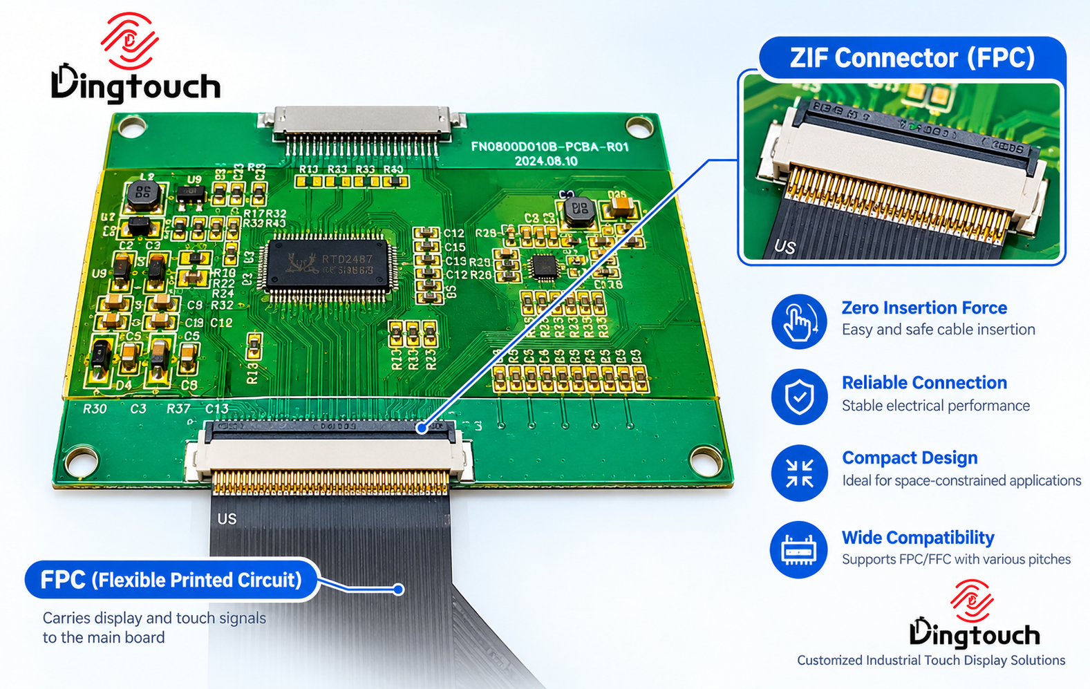
A ZIF connector (Zero Insertion Force connector) is widely used in TFT LCD modules, capacitive touchscreens, and embedded display systems. It provides a compact and convenient way to connect flexible printed circuits while reducing the mechanical force required during cable insertion.
For industrial HMI panels, medical equipment, handheld instruments, and other embedded applications, selecting the right ZIF connector is not simply a matter of matching pin count. Connector orientation, cable routing, mechanical retention, signal integrity, and environmental conditions must also be considered.
At DINGTouch, we provide customized industrial TFT LCD modules, projected capacitive touchscreens, and integrated display solutions. Understanding connector compatibility at the early development stage helps engineers reduce integration risks and build more reliable display systems.
1. What Is a ZIF Connector?
ZIF stands for Zero Insertion Force.
Unlike conventional connectors that require considerable force to insert a cable, a ZIF connector uses a movable locking mechanism that allows a flexible cable to be positioned with minimal resistance.
After the cable is inserted, a locking bar or latch closes to secure the cable and establish electrical contact.
A typical connection process involves four steps:
-
Open the connector's locking mechanism.
-
Insert the FPC or FFC cable into the connector.
-
Close the locking mechanism.
-
Verify that the cable is properly seated and secured.
This design helps reduce the risk of damaging delicate flexible circuits during assembly, making ZIF connectors particularly suitable for thin and compact display modules.
However, zero insertion force does not mean zero mechanical stress after installation. Excessive pulling, twisting, bending, or repeated improper handling can still damage the cable or connector.
2. How Does a ZIF Connector Work in a TFT LCD Module?
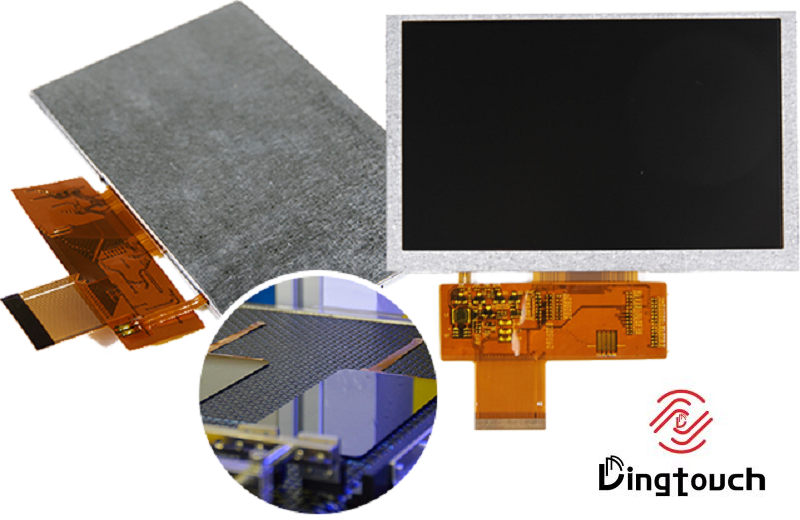
A TFT LCD module typically communicates with a host system through a flexible printed circuit, commonly referred to as an FPC.
The FPC carries the electrical connections required for display operation, including power, control signals, and image data. Depending on the module design, it may also carry touch-related signals.
The exposed conductive contacts on the FPC align with the contacts inside the ZIF connector. When the locking mechanism is closed, controlled pressure maintains contact between the two conductive surfaces.
This connection method provides several practical benefits:
-
Reduced insertion stress: The cable can be inserted without excessive mechanical force.
-
Compact integration: Multiple electrical connections can fit into a relatively small space.
-
Convenient assembly: The cable can be connected or disconnected during production and servicing.
-
Flexible system design: Different display modules can be integrated with compatible host PCBs when their electrical and mechanical specifications match.
For industrial display applications, these advantages help simplify the connection between the display assembly and the main control board.
Nevertheless, the reliability of the connection depends on correct cable insertion, connector compatibility, and proper mechanical support.
3. What Is the Difference Between ZIF, FPC, and FFC?
ZIF, FPC, and FFC are often mentioned together in display integration projects, but they refer to different components.
| Component | Function |
|---|---|
| ZIF Connector | Secures and electrically connects a flexible cable to a PCB |
| FPC | Flexible printed circuit that carries electrical signals |
| FFC | Flat flexible cable used to connect electrical components |
The simplest way to understand the relationship is:
The FPC or FFC is the cable, while the ZIF connector is the interface that connects the cable to the circuit board.
In a TFT LCD module, the display may have an integrated FPC tail. The host PCB then uses a compatible ZIF connector to connect the module to the main system.
Not every FPC or FFC can be used with every ZIF connector. Cable thickness, contact pitch, pin count, contact orientation, and connector design must all be compatible.
4. Why Are ZIF Connectors Commonly Used in TFT LCD Modules?
Modern display assemblies need to accommodate increasingly compact mechanical structures and more complex electrical connections.
ZIF connectors offer a practical balance between connection density, assembly convenience, and mechanical packaging.
4.1 Compact Design for Space-Constrained Applications
Industrial control panels, medical instruments, handheld devices, and embedded systems often have limited internal space.
Compared with larger wire harnesses or conventional board connectors, ZIF connectors can provide multiple electrical connections within a relatively small footprint.
This is particularly useful for:
-
TFT LCD modules with integrated FPC
-
Capacitive touch display assemblies
-
Compact embedded display systems
-
Optical bonding and cover glass integration projects
A properly selected connector helps engineers manage PCB space while maintaining an organized display connection.
4.2 High-Density Signal Connections
Display modules may require multiple power, control, and data connections.
ZIF connectors are available in different contact pitches, including common configurations such as 0.3 mm, 0.5 mm, and 1.0 mm.
Smaller pitch connectors can accommodate more contacts within a limited space, but they also require greater precision during PCB design, cable manufacturing, and assembly.
For higher-speed display interfaces, connector selection must also consider signal integrity, routing, and electromagnetic interference.
4.3 Easier Assembly and Maintenance
A ZIF connector allows a flexible cable to be connected or disconnected without soldering the cable directly to the PCB.
This can simplify manufacturing and make display module replacement more convenient during maintenance.
For equipment with a replaceable display assembly, a properly designed ZIF connection may reduce servicing complexity.
However, the connector should not be treated as a substitute for proper mechanical support. Cable routing and strain relief remain important, especially in industrial environments.
5. Common Types of ZIF Connectors Used in Display Applications
ZIF connectors are available in different mechanical configurations. The appropriate design depends on the available space, cable orientation, assembly process, and host PCB layout.
5.1 Flip-Lock ZIF Connectors
Flip-lock connectors use a movable locking bar that rotates open during cable insertion and closes to secure the cable.
They are commonly used in compact display assemblies because the locking mechanism is relatively straightforward to operate.
During assembly, the locking bar should be opened and closed according to the connector manufacturer's instructions. Excessive force can damage the latch or connector housing.
5.2 Slide-Lock ZIF Connectors
Slide-lock connectors use a locking mechanism that moves outward or inward to release or secure the cable.
Depending on the connector design, this structure may be useful where access to a rotating locking bar is limited.
The required opening and closing direction should be checked before finalizing the enclosure and PCB layout.
5.3 Top-Contact and Bottom-Contact Connectors
One of the most common ZIF connector integration mistakes is selecting the wrong contact orientation.
Some connectors make electrical contact with the exposed conductive pads on the top side of the cable, while others require the pads to face downward.
Even if the connector pitch and pin count are identical, an incorrect contact orientation can prevent the display from operating.
Engineers should confirm:
-
Which side of the FPC contains the exposed contacts
-
Whether the connector uses top-contact or bottom-contact construction
-
The direction in which the cable enters the connector
-
The position of pin 1 and the required cable alignment
These details should be verified using the connector and display module drawings rather than appearance alone.
5.4 Vertical and Right-Angle ZIF Connectors
Connector orientation also affects the mechanical structure of the display assembly.
Vertical connectors and right-angle connectors provide different cable routing options, influencing PCB height, enclosure depth, and available assembly space.
For compact industrial displays, connector orientation should be considered together with the FPC bend radius and the location of other electronic components.
6. How to Select the Right ZIF Connector for a TFT LCD Module
Selecting a connector for a customized TFT LCD module requires evaluating several specifications together.
6.1 Connector Pitch
Pitch refers to the distance between adjacent electrical contacts.
Common display connector pitches include 0.3 mm, 0.5 mm, and 1.0 mm, although other configurations are available.
A smaller pitch allows a higher contact density, but it also requires more precise cable positioning and assembly.
For industrial applications, the optimal pitch should balance available space, manufacturing capability, and long-term connection reliability.
6.2 Pin Count and Pin Assignment
The connector must match the display FPC's pin count and electrical pin assignment.
A connector with the correct pitch but an incompatible pin count or pin mapping cannot be used as a direct replacement.
Engineers should check the complete pin definition, including power, ground, display data, control signals, and touch connections where applicable.
6.3 Cable Thickness and Contact Orientation
FPC thickness and exposed contact orientation are critical compatibility requirements.
The connector must be designed for the actual cable thickness and contact configuration. An incorrect combination may cause insufficient contact pressure, cable movement, or mechanical damage.
Connector specifications and the display module's FPC drawings should be reviewed together.
6.4 Mechanical Space and Cable Routing
The connector's physical dimensions must fit the host PCB and enclosure.
Important considerations include:
-
Available PCB mounting space
-
Connector height and opening clearance
-
Cable insertion direction
-
Minimum FPC bend radius
-
Cable routing near other components
-
Access for assembly and maintenance
In many compact display systems, mechanical constraints can become just as important as electrical interface requirements.
6.5 Environmental Conditions and Mechanical Retention
Industrial equipment may experience vibration, shock, temperature changes, and repeated maintenance.
A ZIF connector that performs well under laboratory conditions may require additional mechanical support when integrated into a demanding environment.
For applications with significant vibration, engineers should evaluate cable retention, connector locking strength, FPC strain relief, and enclosure design together.
7. Common ZIF Connector Problems in TFT LCD Modules
A display that does not operate correctly is not necessarily defective. In some cases, the problem originates from the FPC connection.
7.1 TFT LCD Display Remains Blank
Possible causes include:
-
FPC not fully inserted
-
Incorrect contact orientation
-
Damaged connector contacts
-
Broken locking mechanism
-
Incorrect pin assignment
Before replacing the display module, the connection should be inspected according to the manufacturer's servicing instructions.
7.2 Display Works but Touch Function Does Not Respond
Some integrated display solutions use separate electrical connections for the LCD and projected capacitive touch panel.
If the display image is normal but touch functionality is unavailable, the touch FPC, touch controller connection, or related electrical interface may require inspection.
The exact cause depends on the module's electrical architecture.
7.3 Intermittent Display or Touch Operation
A display may function correctly during initial testing but experience intermittent failures after installation.
Possible contributing factors include:
-
Cable strain or excessive bending
-
Incomplete connector locking
-
Vibration-induced cable movement
-
Poor mechanical support
-
Incorrect cable routing
For industrial display projects, connection stability should be evaluated as part of the complete assembly rather than as an isolated connector specification.
7.4 Broken ZIF Locking Mechanism
Although ZIF connectors are designed to simplify cable insertion, their locking mechanisms can be damaged by excessive force.
A broken latch may prevent the cable from remaining securely positioned, resulting in intermittent electrical contact.
If the locking mechanism is damaged, replacement of the connector or affected assembly may be necessary. Attempting to force the cable into a damaged connector can create additional problems.
8. Are ZIF Connectors Suitable for High-Speed Display Interfaces?
ZIF connectors are used in a wide range of display assemblies, but their suitability for high-speed interfaces depends on the connector's electrical characteristics and the overall system design.
For interfaces such as MIPI DSI, LVDS, and eDP, engineers should evaluate:
-
Connector signal integrity and electrical specifications
-
PCB trace impedance and routing
-
FPC length and construction
-
Differential pair routing where applicable
-
Electromagnetic interference and compatibility
-
Grounding and return paths
A connector that works well with a low-speed control interface may not necessarily be suitable for a higher-speed display data connection.
For this reason, connector selection should be verified against the actual display interface, operating speed, cable configuration, and host PCB design.
9. Are ZIF Connectors Always the Best Choice for Industrial Displays?
Not necessarily.
ZIF connectors are a practical solution for many TFT LCD modules and touch display assemblies, particularly when compact dimensions and convenient servicing are important.
However, applications with extreme vibration, frequent mechanical movement, or demanding environmental conditions may require a different connection method or additional retention measures.
Depending on the project, alternatives may include board-to-board connectors, specialized cable assemblies, or direct soldered connections.
The correct solution depends on the display interface, enclosure structure, maintenance requirements, and environmental conditions.
This is why connector selection should be evaluated as part of the overall display integration process.
10. How DINGTouch Supports TFT LCD Module Integration
At DINGTouch, we specialize in industrial TFT LCD modules, projected capacitive touchscreens, cover glass customization, and optical bonding solutions for OEM and ODM projects.
Connector compatibility is an important consideration when developing a customized display assembly.
During project evaluation, the following details can help determine the appropriate display and connection solution:
-
Display size and resolution
-
Required interface, such as MIPI DSI, LVDS, RGB, or eDP
-
FPC dimensions and connector specifications
-
touchscreen requirements and touch interface
-
PCB and enclosure constraints
-
Operating temperature and environmental conditions
When a project requires a customized FPC, connector position, or display integration structure, these requirements should be reviewed early in the development process.
By considering the display module, touch panel, optical bonding structure, and host PCB together, engineers can reduce compatibility risks and avoid unnecessary redesigns during later development stages.
For customized industrial display projects, contact DINGTouch to discuss your display specifications and integration requirements.
Website: www.szdingtouch.com
Email: sales@szdingtouch.com
Frequently Asked Questions About ZIF Connectors
How many insertion cycles can a ZIF connector typically withstand?
The number of insertion cycles depends on the connector design, materials, locking mechanism, and manufacturer specifications.
Some ZIF connectors are designed for dozens or hundreds of insertion cycles, while other models may have different durability ratings.
For industrial equipment that requires frequent maintenance or display replacement, engineers should verify the specified mating-cycle rating before selecting the connector.
Can vibration loosen a ZIF connector over time?
A properly locked ZIF connector helps maintain electrical contact, but vibration can still affect connection reliability if cable routing or mechanical support is inadequate.
In industrial applications, connector retention should be evaluated together with FPC strain relief, enclosure design, and the expected vibration environment.
Additional retention measures may be required depending on the application.
Is a ZIF connector suitable for high-speed display interfaces?
It depends on the connector's electrical specifications and the display interface.
ZIF connectors are used in many display applications, but higher-speed interfaces require careful evaluation of signal integrity, cable length, impedance, EMI performance, and PCB routing.
The connector should be verified against the actual interface requirements rather than selected solely by pitch or pin count.
What is the most common cause of ZIF connector failure?
Mechanical damage and improper cable handling are important causes of ZIF connector problems.
Typical issues include broken locking tabs, incomplete cable insertion, excessive force during servicing, incorrect contact orientation, and cable strain.
Correct assembly procedures and suitable mechanical support can help reduce these risks.
Should the ZIF connector be selected before or after the display module?
Ideally, connector selection should be considered together with the display module, host PCB, enclosure design, and assembly process.
Selecting the connector too late may introduce mechanical constraints or require changes to the FPC and PCB layout.
For customized TFT LCD projects, confirming the connector and FPC requirements during the initial design stage is generally the more efficient approach.
Conclusion
ZIF connectors are widely used in TFT LCD modules because they provide a compact, convenient, and practical method for connecting flexible circuits to host PCBs.
However, reliable display integration requires more than matching the connector pitch and pin count. Contact orientation, FPC thickness, cable routing, signal integrity, mechanical retention, and environmental conditions all influence long-term performance.
For industrial display projects, these small connection details can make a significant difference to assembly efficiency, maintenance, and system reliability.
DINGTouch supports customized TFT LCD modules, industrial capacitive touchscreens, and integrated display solutions, helping OEM customers evaluate display specifications and connection requirements from the early stages of development.
DINGTouch — Customized Industrial Touch Display Solutions
Ready to Build Your Outdoor Display Solution?
Get in touch with us at sales@szdingtouch.com. Our expert engineers will help you design a cost-effective, tailored solution to meet your project’s exact specifications.
DINGTouch:Committed to continuous innovation and improvement of product quality to meet customers' high requirements and expectations.
DINGTouch is a manufacturer that provides high quality touch screen panels. Focus on the design, manufacturing and sales of touch screen panels, and are committed to providing customized solutions that satisfy customers.
DINGTouch: In the process of customizing touch screen panels, we focus on close cooperation and communication with customers. Understanding customers' needs and providing customized solutions will meet customers' individual needs. The company's products are favored by customers for their high quality and reliability, and provide them with the best touchscreen panel solutions.
DINGTouch is a company specializing in the R&D and production of touch screen technology, headquartered in Shenzhen, China. As a professional touch screen supplier, DINGTouch is committed to providing high-quality, stable and reliable touch screen products to meet the diverse needs of customers. We continue to carry out technological innovation and product optimization to ensure that its touch screen products have good sensitivity, accuracy and durability.
In addition to the products themselves, we also focus on cooperation and communication with customers, and are committed to providing customized solutions and excellent after-sales services. Through continuous efforts to improve product quality and customer satisfaction, we have established a good reputation in the touchscreen industry and won widespread market recognition.
• PCAP maximum size 65”
• Multi-touch (Touch screen can be customized to your needs.)
• Optical bonding service/air bonding
• LCD interface: HDMI/RGB/MIPI/LVDS/EDP, etc.
• PCAP interface: IIC/USB interface
• CTP can customize the cover glass surface treatment process AG (anti-glare), AR (anti-reflection), AF (anti-fingerprint), waterproof, and glove touch
• Supports 0.55 mm-12 mm coverslip touch.
• Support operating temperature: -40℃-90℃.
In conclusion, Dingtouch as a professional touch screen manufacturer with more than 10 years touch screen experience.We have many capacitive touch screen. Such as 5 inch touch screen,7 inch touch screen,10.1inch touch screen,15 inch touch screen,15.6 inch touch screen,17 inch touch screen,18.5 inch touch screen,19 inch touch screen,21.5 inch touch screen,32 inch touch screen, However, we also welcome to customize your own touch screen . Contact our team today to learn what capacitive touch screen are best for our retail business needs.
Contact us NOW! sales@szdingtouch.com
#Medicaltouchscreencalibration, #capacitivetouchcalibrationguide, #IEC60601touchscreen, #DINGTouchmedicaldisplay, #touchscreenaccuracy, #touchscreen driftfix, #medicalequipmenttouchsolutions, #IP65touchpanel, #IK10medicaltouchscreen, #glove touch medical monitor,#ILITEKTouchControllerICSelectionGuide ,#OCAtoOCR #GT911,#CustomizedWideTemperatureTouchScreenSolutions,#Waterproof Touchscreen,
#highbrightnessLCD, #sunlightreadabledisplay,#industrialLCDbacklight, #outdoor displaymodule, #customLCDsolution, #1000–2000nitsdisplay, #DINGTouchtouchscreen.
DINGTouch — Custom Touch Display Solutions Expert
Every touch, clear and precise, ready for any environment.




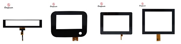
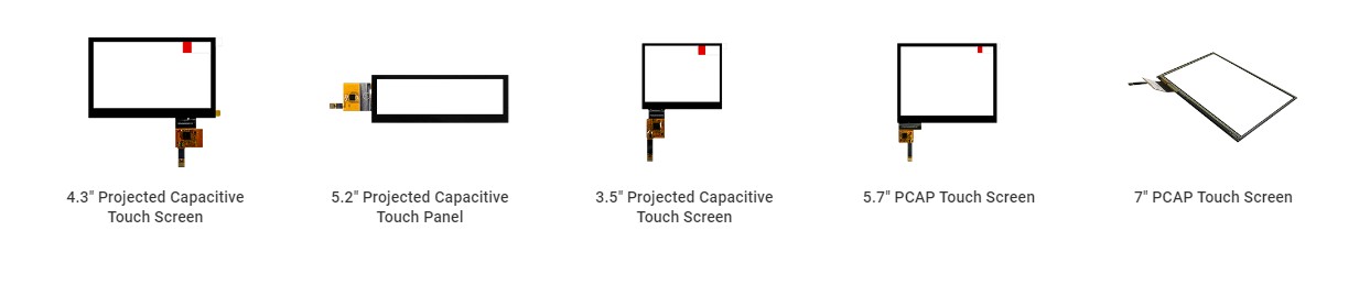
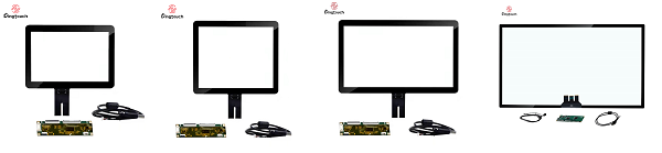
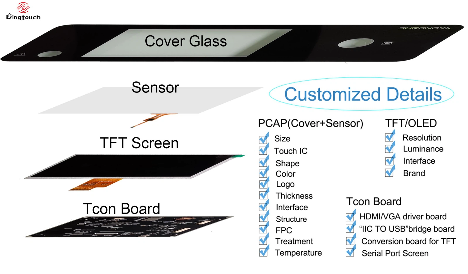
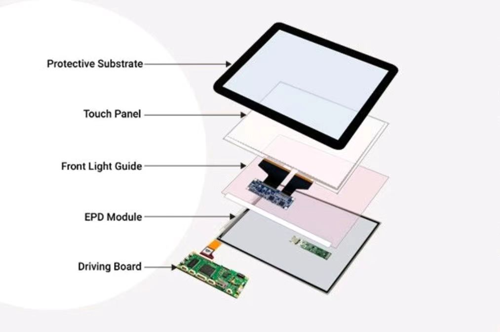
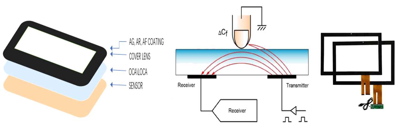
What DINGTOUCH can do:
Dingtouch Industrial capacitive touch screen Manufacturer
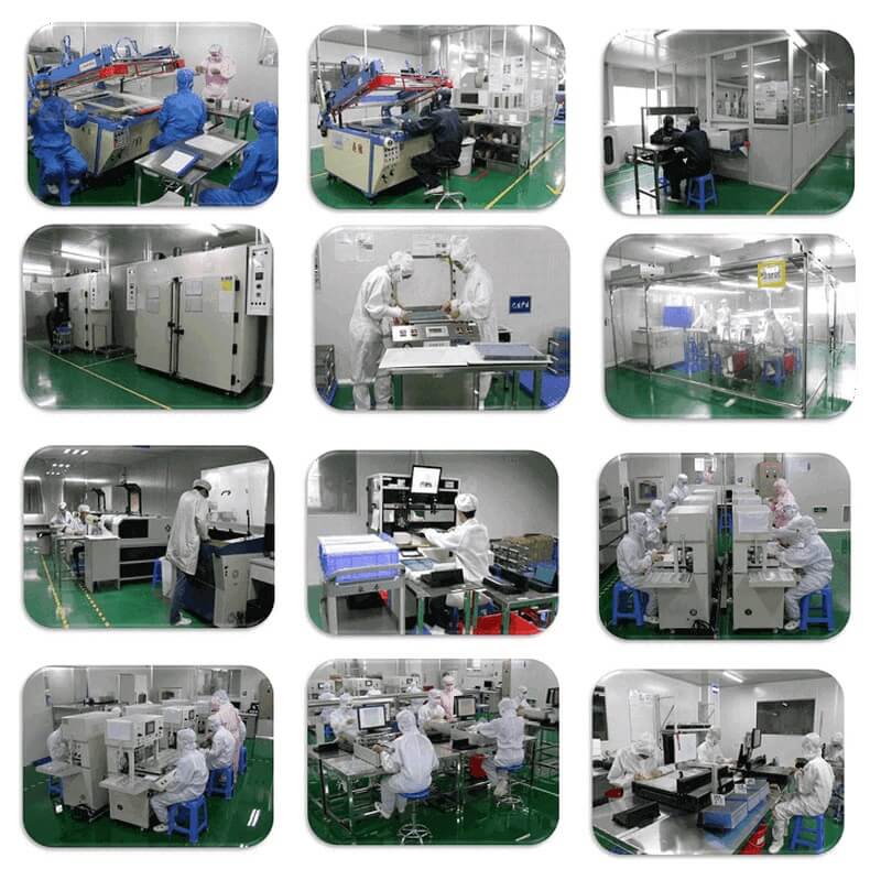

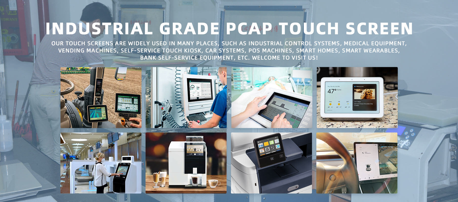
CATEGORIES
CONTACT US
Contact: Dingtouch
Phone: +8615815536116
Tel: +8615815536116
Email: sales@szdingtouch.com
Add: Building A, Bailu Plaza, No. 48, Gonghe Industrial Road, Gongle Community, Xixiang Street, Baoan District, Shenzhen,China. 518126
 Dingtouch