News
Can a Medical Touch Display Pass EMC Testing? A Practical Guide to IEC 60601-1-2 Compliance


Can a Medical Touch Display Pass EMC Testing? A Practical Guide to IEC 60601-1-2 Compliance
Understanding EMI, EMS, and Display Integration Risks in Medical Device Design
When developing medical equipment, selecting a suitable display involves much more than resolution, brightness, touch sensitivity, and viewing angle.
One important question often raised by medical device engineers is:
Can a medical touch display pass EMC certification?
The short answer is that an individual touch display module generally cannot guarantee compliance with medical EMC requirements independently. Electromagnetic compatibility (EMC) testing is normally conducted on the complete medical electrical equipment or system, with the display assembly evaluated as part of the integrated design.
However, this does not mean the display is electrically insignificant.
In fact, the combination of LCD driving circuits, LED backlight systems, capacitive touch controllers, FPC cables, and grounding structures can introduce electromagnetic interference (EMI) or reduce electromagnetic immunity (EMS).
For medical equipment manufacturers, choosing and integrating the right display solution early in development can significantly reduce EMC-related design risks.
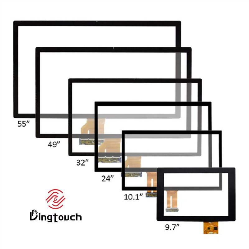
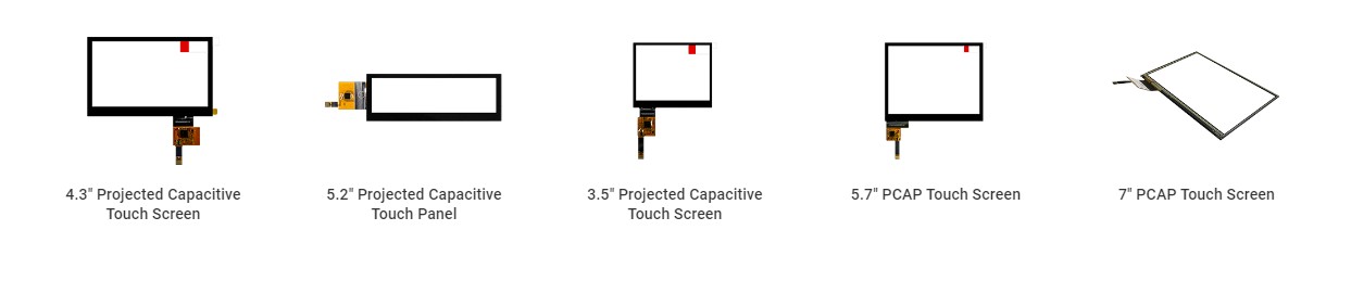
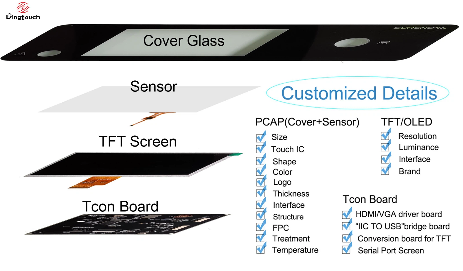
At DINGTouch, we provide customized industrial and medical touch display solutions, integrating TFT LCD panels, projected capacitive touchscreens, cover glass, and optical bonding. Understanding the relationship between display architecture and EMC performance is an important part of our engineering approach.
This article explains the major EMC challenges associated with medical touch displays and the practical considerations that engineers should address before certification testing.
1. What Does IEC 60601-1-2 Mean for Medical Touch Displays?
IEC 60601-1-2 is the collateral standard addressing electromagnetic disturbances for medical electrical equipment and medical electrical systems.
Its primary objective is to ensure that medical equipment operates safely and reliably in the presence of electromagnetic disturbances while limiting the electromagnetic emissions it generates.
Medical EMC evaluation generally involves two essential aspects:
Electromagnetic emissions (EMI)
The equipment must control electromagnetic emissions to avoid interfering with other electronic devices.
Electromagnetic immunity (EMS)
The equipment must maintain essential performance and acceptable operation when exposed to electromagnetic disturbances.
Depending on the device classification and intended environment, EMC evaluation may include:
-
Conducted emissions
-
Radiated emissions
-
Electrostatic discharge (ESD)
-
Electrical fast transient/burst (EFT)
-
Surge immunity
-
Conducted RF immunity
-
Radiated RF immunity
-
Power-frequency magnetic field immunity
-
Voltage dips and interruptions, where applicable
The applicable test levels and performance criteria depend on the medical device, its intended use, and the relevant edition of the standard.
For example, a bedside patient monitor, portable ultrasound system, infusion pump, and surgical control console may have very different EMC design requirements.
Therefore, medical display selection should always consider the actual equipment architecture and operating environment rather than relying on a generic EMC specification.
2. Why Is the Display Assembly an Important EMC Consideration?
A medical touch display is not simply a passive visual component.
A typical integrated display assembly may contain several electrically active or interconnected elements:
-
TFT LCD panel and timing control circuitry
-
LED backlight and driver circuit
-
Projected capacitive (PCAP) touch sensor
-
Touch controller and firmware
-
Flexible printed circuit (FPC)
-
Display interface connections
-
Power and grounding connections
-
Conductive shielding structures
Each component can influence electromagnetic behavior.
For example, a high-speed display interface may generate unwanted emissions, while an improperly grounded touch sensor may become more susceptible to external interference.
Similarly, a backlight driver with insufficient filtering may introduce switching noise into the power supply.
The important point is that EMC performance depends on how these components work together.
A display module that performs well during normal functional testing may still introduce problems when integrated into the final medical device.
3. Five Common EMC Risks in Medical Touch Display Integration
3.1 LED Backlight Drivers: A Potential Source of Switching Noise
High-brightness medical displays often require powerful LED backlight systems.
Most LED backlight drivers use switching regulators, such as boost converters, to provide the required voltage and current.
Although these circuits are efficient, their switching operation can generate electromagnetic noise.
If the circuit layout or filtering design is inadequate, interference may propagate through:
-
Power supply lines
-
Ground connections
-
FPC cables
-
Nearby signal circuits
-
Conductive structures within the enclosure
This can contribute to conducted or radiated emissions problems.
The challenge can become more significant in high-brightness display applications, where increased backlight power may require more demanding driver designs.
DINGTouch engineering considerations:
When developing high-brightness medical touch display assemblies, several factors should be evaluated:
-
LED driver topology and switching frequency
-
Power filtering and decoupling
-
Separation between backlight power and touch signals
-
PCB grounding and return-current paths
-
Cable routing and shielding
-
Backlight performance under different operating conditions
The objective is not simply to achieve higher brightness, but to balance optical performance, power consumption, thermal behavior, and electromagnetic compatibility.
3.2 FPC Cables: Small Components with Significant EMC Impact
Flexible printed circuits are widely used to connect LCD panels, touch sensors, and controller boards.
Their compact structure makes them suitable for space-constrained medical equipment, but poorly designed FPC routing can create unexpected EMC problems.
Potential risks include:
-
Excessive cable length
-
Insufficient ground reference
-
Poor signal return paths
-
Inadequate shielding
-
Improper routing near switching power circuits
-
Crosstalk between high-speed signals
Long or poorly routed cables may behave as unintended antennas, increasing radiated emissions or making signal transmission more susceptible to interference.
Possible engineering improvements include:
-
Optimizing FPC length and routing
-
Adding ground reference layers
-
Improving differential signal routing
-
Introducing shielding films where appropriate
-
Separating sensitive touch signals from noisy power circuits
-
Optimizing connector and grounding arrangements
For medical equipment with moving displays, folding structures, or compact internal layouts, mechanical requirements must also be considered.
The best FPC solution should satisfy electrical performance, mechanical flexibility, assembly requirements, and long-term reliability simultaneously.
3.3 Capacitive touchscreens: Maintaining Stable Touch Performance Under Interference
Projected capacitive touch technology (PCAP) is widely used in modern medical equipment because it offers responsive operation, multi-touch capability, and a flat, easy-to-clean front surface.
However, capacitive touchscreens detect changes in electrical capacitance, making their performance dependent on the surrounding electrical environment.
Electromagnetic disturbances may cause:
-
False touch activation
-
Missed touch events
-
Touch coordinate drift
-
Intermittent touch response
-
Reduced sensitivity
-
Unstable operation during ESD events
These problems can become more noticeable in medical equipment where multiple electronic subsystems operate within a compact enclosure.
Touch performance also depends on the cover glass structure, sensor design, grounding, and controller configuration.
For example, thicker cover glass, protective overlays, gloves, moisture, and different installation conditions may require adjustments to touch sensitivity and firmware parameters.
DINGTouch customization considerations include:
-
Selecting suitable touch controller IC
-
Optimizing sensor electrode structures
-
Adjusting touch sensitivity and filtering parameters
-
Improving grounding and shielding arrangements
-
Evaluating glove and moisture operation
-
Testing touch stability under relevant interference conditions
A higher touch sensitivity setting does not necessarily produce better overall performance.
For medical applications, stable and predictable touch operation is often more important than maximizing sensitivity.
3.4 Grounding and Shielding: The Foundation of EMC Stability
Grounding is one of the most important factors in medical display integration.
Even a well-designed LCD and touch module can experience EMC problems if the grounding architecture of the complete device is poorly planned.
Common issues include:
-
Floating conductive shielding layers
-
Inconsistent ground connections
-
Multiple unintended ground paths
-
High-impedance return-current paths
-
Poor electrical contact between the display frame and enclosure
-
Inadequate separation between noisy and sensitive circuits
Simply adding more shielding materials does not automatically improve EMC performance.
Shielding effectiveness depends on proper electrical bonding, continuity, grounding, and the overall current return-path design.
For medical touch display integration, engineers should evaluate:
-
The grounding relationship between the LCD, touch sensor, and controller.
-
Electrical continuity between conductive shielding layers and the device enclosure.
-
The routing of power and signal return currents.
-
The connection between the display assembly and the mainboard.
-
Potential ground loops caused by different system connections.
A coordinated grounding and shielding strategy is generally more effective than adding shielding components without considering the complete electrical architecture.
3.5 Display Interface Selection: RGB, LVDS, MIPI DSI, or eDP?
The display interface can influence signal integrity, cable design, and electromagnetic emissions.
Different interfaces have different electrical characteristics and integration requirements.
| Display Interface | Main Characteristics | EMC Design Considerations |
|---|---|---|
| RGB Parallel | Multiple parallel data and control signals | More signal lines and careful routing requirements |
| LVDS | Differential signal transmission | Controlled impedance, pair matching, and common-mode noise control |
| MIPI DSI | High-speed differential serial interface | Strict PCB layout, impedance, and signal integrity requirements |
| eDP | High-bandwidth embedded display interface | High-speed routing and connector design require attention |
Why is LVDS frequently considered for medical display projects?
LVDS uses differential signaling, which can help reduce electromagnetic emissions when implemented with appropriate routing and termination.
It is also a mature interface with broad adoption in industrial and embedded display applications.
MIPI DSI offers advantages in compact systems where high-resolution displays and limited connector space are important.
eDP is suitable for applications requiring higher display bandwidth, while RGB parallel interfaces remain useful in certain embedded architectures.
However, no interface can guarantee EMC compliance by itself.
The final selection should consider:
-
Display resolution and refresh rate
-
Processor and motherboard compatibility
-
Cable length and connector structure
-
PCB layout capability
-
Enclosure dimensions
-
Signal integrity requirements
-
Overall EMC test margins
For this reason, DINGTouch supports different display interfaces according to customer system architecture and project requirements.
4. Why Can a Medical Device Pass Functional Testing but Fail EMC Testing?
This is a common challenge during medical device development.
A prototype may display images correctly, respond to touch normally, and operate continuously without obvious problems.
However, during EMC testing, unexpected behavior may appear.
Typical examples include:
| EMC Test or Condition | Possible Display-Related Problem |
|---|---|
| ESD | Touch malfunction, false triggering, or temporary display disturbance |
| Radiated RF immunity | Touch instability or communication errors |
| Conducted RF immunity | Power or signal interference |
| Radiated emissions | Peaks associated with high-speed display signals or backlight switching |
| EFT/Burst | Temporary display reset or unstable touch response |
| Power disturbances | Backlight flickering or display interruption |
These symptoms do not necessarily mean the display module is defective.
The actual cause may involve the mainboard, power architecture, cable routing, enclosure grounding, or interactions between different subsystems.
Mechanical changes can also introduce new EMC risks.
For example, replacing a short FPC with a longer cable, changing the enclosure material, or modifying the display mounting structure may affect the original EMC performance.
This is why EMC evaluation should be included throughout product development rather than postponed until final certification.
5. How to Reduce EMC Risks Before Medical Device Certification
A structured engineering process can help identify potential problems earlier and reduce expensive redesign work.
We recommend considering the following stages.
Step 1: Define the Medical Device EMC Requirements
Identify the applicable IEC 60601-1-2 edition, intended operating environment, essential performance requirements, and relevant test conditions.
Step 2: Evaluate the Complete Display Architecture
Review the LCD panel, touch sensor, controller, backlight driver, FPC, connectors, and power requirements.
Step 3: Review Grounding and Shielding
Evaluate conductive structures, grounding connections, signal return paths, and the relationship between the display assembly and the main enclosure.
Step 4: Optimize Interface and Cable Design
Select suitable display interfaces and optimize cable length, routing, shielding, and signal integrity.
Step 5: Perform Pre-Compliance Testing
Use preliminary EMC testing to identify emission and immunity problems before formal certification.
Step 6: Validate the Final Integrated Configuration
After hardware, mechanical, and firmware modifications, verify the complete device under the applicable test conditions.
One important consideration: any modification to the display assembly should be evaluated within the actual device configuration, particularly when it affects power consumption, grounding, cables, or shielding.
6. What Can a Medical Touch Display Manufacturer Do to Support EMC Design?
A display manufacturer cannot independently guarantee that a complete medical device will pass IEC 60601-1-2 testing.
The final result depends on the entire system and its intended operating environment.
However, an experienced display integration manufacturer can help customers reduce potential EMC risks during the design and development stages.
At DINGTouch, our medical and industrial touch display customization capabilities cover multiple aspects of display integration.
Our engineering support can include:
Custom TFT LCD and touchscreen Integration
-
TFT LCD selection according to resolution, brightness, and operating temperature requirements
-
PCAP touchscreen customization
-
Touch controller and interface selection
-
Customized FPC and connector configurations
Cover Glass and Optical Bonding
-
Customized cover glass dimensions and thickness
-
Chemically strengthened cover glass options
-
AG, AR, and AF surface treatments
-
OCA and LOCA optical bonding
-
Full-lamination display assemblies
EMC-Oriented Integration Considerations
-
Review of display signal interfaces
-
FPC routing and grounding recommendations
-
Touch controller configuration and sensitivity optimization
-
Conductive shielding structure considerations
-
Backlight power and filtering considerations
-
Technical support during prototype evaluation and pre-compliance troubleshooting
By integrating the display, touchscreen, cover glass, and optical bonding requirements during development, potential interface and structural conflicts can be identified earlier.
This is particularly valuable for customized medical equipment where display dimensions, enclosure structures, touch behavior, and electrical interfaces are not standardized.
7. Medical Touch Display Customization: Why Project-Specific Engineering Matters
Different medical devices require different display configurations.
A portable medical monitor may prioritize low power consumption, compact dimensions, and reliable battery operation.
An ultrasound system may require a larger high-resolution touchscreen with responsive multi-touch performance.
A surgical control console may require high brightness, excellent optical clarity, and stable operation in an electrically complex environment.
Therefore, selecting a display based only on size and resolution is often insufficient.
A complete project evaluation should consider:
-
Display size and resolution
-
Brightness and viewing angle
-
Touch technology and number of touch points
-
Cover glass material and thickness
-
Optical bonding requirements
-
Operating temperature
-
Display interface and touch interface
-
Power consumption
-
Mechanical installation
-
Grounding and shielding requirements
At DINGTouch, we focus on customized touch display assemblies for industrial and medical equipment manufacturers.
Our product and engineering scope includes TFT LCD panels, PCAP touchscreens, touch display assemblies, customized cover glass, and optical bonding solutions.
We work with customers to evaluate display configurations based on their actual application and system requirements.
Frequently Asked Questions (FAQ)
Can a medical touchscreen display pass IEC 60601-1-2 certification independently?
Generally, no. IEC 60601-1-2 compliance is evaluated at the medical electrical equipment or system level. An individual display module can undergo component-level testing or evaluation, but this does not replace the EMC assessment of the final medical device.
Why do medical capacitive touchscreens sometimes fail ESD testing?
ESD events can introduce transient electrical disturbances into the touch sensor, controller, grounding network, and connected cables. Poor grounding, inadequate shielding, and unsuitable controller configurations may contribute to false touches or temporary touch malfunction.
Is LVDS better than MIPI for medical display EMC performance?
LVDS can offer advantages because of its differential signaling and mature integration practices. However, MIPI DSI is also suitable for medical equipment when the PCB layout, impedance control, grounding, and cable structure are properly designed. Neither interface guarantees EMC compliance independently.
Does optical bonding improve EMC performance?
Optical bonding is primarily used to improve optical clarity, reduce internal reflections, and enhance mechanical integration. It is not an EMC protection method by itself. EMC performance still depends on grounding, shielding, circuit design, and cable configuration.
Are high-brightness medical displays more difficult to optimize for EMC?
They can be. Higher brightness may require increased backlight power and more demanding LED driver circuits, potentially introducing additional switching noise. Appropriate driver selection, filtering, PCB layout, and grounding are important.
Can DINGTouch provide EMC-certified medical touch displays?
DINGTouch provides customized medical and industrial touch display assemblies and supports project-specific engineering evaluations. However, EMC compliance must be verified on the final integrated medical device. Display-level testing and supporting technical information can be discussed according to project requirements.

Conclusion: EMC Should Be Considered from the Beginning of Medical Display Design
Medical EMC performance is not determined by a single component.
The LCD panel, LED backlight, capacitive touch sensor, FPC cables, display interface, grounding architecture, and enclosure structure all contribute to the electromagnetic behavior of the final device.
A display that performs perfectly during normal operation may still introduce problems during ESD, radiated immunity, or emissions testing if its integration is not properly considered.
For medical equipment manufacturers, the most effective approach is to evaluate display-related EMC risks early, select suitable interfaces and components, and validate the complete system before formal certification.
DINGTouch provides customized TFT LCD, PCAP touchscreen, cover glass, and optical bonding solutions for industrial and medical equipment applications.
If your medical device project requires a customized touch display, our engineering team can help evaluate display specifications, touch configurations, interface options, and EMC-related integration considerations.
Contact DINGTouch to discuss your medical touch display project.



Ready to Build Your Outdoor Display Solution?
Get in touch with us at sales@szdingtouch.com. Our expert engineers will help you design a cost-effective, tailored solution to meet your project’s exact specifications.
DINGTouch:Committed to continuous innovation and improvement of product quality to meet customers' high requirements and expectations.
DINGTouch is a manufacturer that provides high quality touch screen panels. Focus on the design, manufacturing and sales of touch screen panels, and are committed to providing customized solutions that satisfy customers.
DINGTouch: In the process of customizing touch screen panels, we focus on close cooperation and communication with customers. Understanding customers' needs and providing customized solutions will meet customers' individual needs. The company's products are favored by customers for their high quality and reliability, and provide them with the best touchscreen panel solutions.
At DINGTOUCH, we are the world's leading touchscreen manufacturer, helping businesses around the world take advantage of this exciting technology. For more information, please visit the home page now.

DINGTouch is a company specializing in the R&D and production of touch screen technology, headquartered in Shenzhen, China. As a professional touch screen supplier, DINGTouch is committed to providing high-quality, stable and reliable touch screen products to meet the diverse needs of customers. We continue to carry out technological innovation and product optimization to ensure that its touch screen products have good sensitivity, accuracy and durability.
In addition to the products themselves, we also focus on cooperation and communication with customers, and are committed to providing customized solutions and excellent after-sales services. Through continuous efforts to improve product quality and customer satisfaction, we have established a good reputation in the touchscreen industry and won widespread market recognition.
In addition to the products themselves, we also focus on cooperation and communication with customers, and are committed to providing customized solutions and excellent after-sales services. Through continuous efforts to improve product quality and customer satisfaction, we have established a good reputation in the touchscreen industry and won widespread market recognition.
What DINGTOUCH can do:
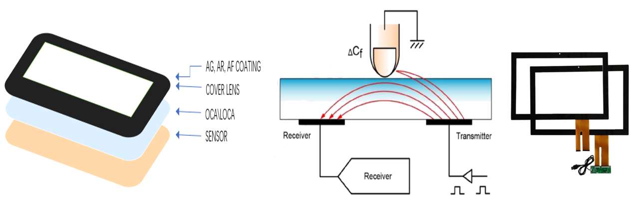
• PCAP maximum size 65”
• Multi-touch (Touch screen can be customized to your needs.)
• Optical bonding service/air bonding
• LCD interface: HDMI/RGB/MIPI/LVDS/EDP, etc.
• PCAP interface: IIC/USB interface
• CTP can customize the cover glass surface treatment process AG (anti-glare), AR (anti-reflection), AF (anti-fingerprint), waterproof, and glove touch
• Supports 0.55 mm-12 mm coverslip touch.
• Support operating temperature: -40℃-90℃.
CATEGORIES
CONTACT US
Contact: Dingtouch
Phone: +8615815536116
Tel: +8615815536116
Email: sales@szdingtouch.com
Add: Building A, Bailu Plaza, No. 48, Gonghe Industrial Road, Gongle Community, Xixiang Street, Baoan District, Shenzhen,China. 518126
 Dingtouch