News
GF vs. GFF vs. GF2 vs. G1F vs. GG vs. OGS: A Complete Guide to Touch Screen Technologies
GF vs. GFF vs. GF2 vs. G1F vs. GG vs. OGS: A Complete Guide to Touch Screen Technologies
Understanding Touch Sensor Structures, Advantages, Disadvantages, and Applications
When sourcing a custom capacitive touch screen, have you ever wondered what GF, GFF, GF2, G1F, GG, OGS, On-cell, and In-cell actually mean?
These abbreviations describe different touch sensor structures and integration methods. Although they may look similar, they can differ in material composition, manufacturing processes, optical performance, thickness, touch functionality, development costs, and design flexibility.
For industrial control panels, medical equipment, outdoor terminals, and smart devices, choosing the right touch screen structure is not simply a matter of comparing prices. Engineers and OEM buyers must also consider cover glass requirements, touch performance, environmental conditions, display integration, and long-term product reliability.
As a manufacturer specializing in industrial capacitive touch screens and customized touch display solutions, DINGTouch explains the key differences between these technologies to help you make a more informed decision.
1. Understanding the Basic Structure of a Touch Display
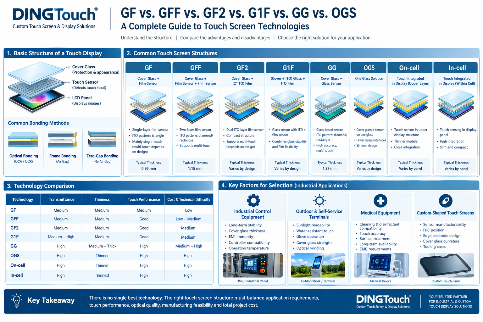
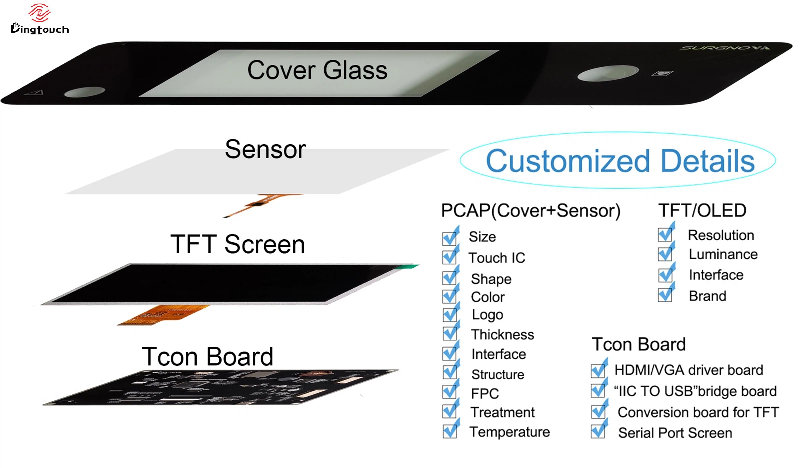
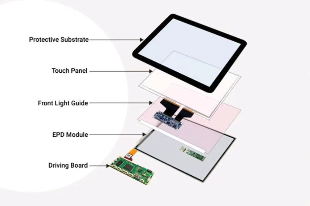
A typical capacitive touch display consists of three main components:
-
Cover Glass (CG): Protects the touch surface and provides the desired appearance, shape, and surface finish.
-
Touch Sensor (TP Sensor): Detects the position of a finger or another compatible touch object.
-
LCD Panel: Displays images, text, and the graphical user interface.
These components can be combined in different ways depending on the required touch sensor structure and display integration method.
Common Touch Display Bonding Methods
1. Optical Bonding
Optical bonding uses an optical adhesive, such as OCA or OCR, to bond designated layers and eliminate the air gap at the bonded interface. It can reduce internal reflections, improve sunlight readability, and enhance the overall integration of the display module.
2. Frame Bonding
Frame bonding secures the touch assembly to the display around the perimeter while leaving an air gap between the components. It can simplify certain manufacturing and service processes, although the air gap may increase reflections.
3. Zero-Gap Bonding
Zero-gap bonding generally refers to a design that eliminates a specific air gap between components. The exact meaning depends on the manufacturer's terminology and the module structure, so the bonding interfaces should always be clearly defined.
Important: GF, GFF, GG, and OGS describe touch sensor structures or integration approaches, while optical bonding and frame bonding describe how components are assembled. These are different technical dimensions and should not be confused.
2. What Do GF, GFF, GF2, G1F, GG, OGS, On-cell, and In-cell Mean?
The following table summarizes common definitions. Exact layer arrangements may vary between manufacturers, especially for GF2 and G1F.
| Technology | Typical Structure | Key Characteristics |
|---|---|---|
| GF | Cover Glass + Film Sensor | Single-layer film sensor |
| GFF | Cover Glass + Film Sensor + Film Sensor | Dual-layer film sensor |
| GF2 | Cover Glass + a dual-ITO-layer film sensor structure | Two conductive electrode layers implemented in a specific film structure |
| G1F | Glass sensor with ITO + Film Sensor | Hybrid glass-and-film structure |
| GG | Cover Glass + Glass Sensor | Glass-based touch sensor |
| OGS | One Glass Solution | Cover glass and touch sensor integrated on one glass substrate |
| On-cell | Touch sensor integrated above the display cell | Touch functionality integrated into the upper display structure |
| In-cell | Touch functionality integrated within the display cell | Highly integrated display and touch architecture |
Because industry terminology is not always standardized, buyers should confirm the actual cross-sectional drawing, sensor materials, ITO layer arrangement, and electrode design rather than relying on abbreviations alone.
3. GF Technology: Single-Layer Film Sensor
GF generally stands for Cover Glass + Film Sensor. This structure combines a cover glass with a single-layer film-based touch sensor.
Depending on the electrode design, the sensor may use a specific ITO pattern to detect touch input. Multi-touch capability depends on the electrode layout, controller, firmware, and overall system design; it should not be assumed that all GF sensors are limited to single-touch operation.
Advantages of GF Touch Screens
-
Relatively simple structure with potential cost advantages.
-
Thin sensor construction for applications requiring a compact design.
-
Flexible sensor pattern design for selected custom shapes.
-
Suitable for projects that prioritize cost, thickness, and basic touch functionality.
Limitations of GF Technology
-
Multi-touch performance depends on the sensor architecture and controller.
-
Optical performance and mechanical stability must be evaluated for the selected materials.
-
Electromagnetic interference, grounding, and environmental conditions may affect touch performance.
Typical applications: Cost-sensitive electronic devices, basic human-machine interfaces, and selected custom touch screen projects.
4. GFF Technology: Dual-Layer Film Sensor
GFF generally consists of a cover glass and two film sensor layers. The two sensor layers can provide different electrode directions for projected capacitive touch detection.
Advantages of GFF Touch Screens
-
Suitable for multi-touch applications.
-
Flexible electrode and sensor pattern design.
-
Potentially competitive tooling and development costs for selected custom projects.
-
Touch parameters can be optimized for specific operating requirements.
Limitations of GFF Technology
-
Optical performance may differ from that of certain glass sensor structures.
-
Additional material interfaces can affect total thickness, transmittance, and haze.
-
Actual touch accuracy and noise immunity depend on the electrode design, controller, and host system.
Typical applications: Industrial control panels, smart terminals, custom-shaped touch screens, and devices requiring multi-touch functionality.
5. GG Technology: Glass-Based Touch Sensor
GG generally stands for Cover Glass + Glass Sensor. The structure combines a cover glass with a separate glass-based touch sensor.
The ITO electrodes on the sensor glass are arranged to detect touch positions. GG is widely used in industrial, commercial, and customized capacitive touch applications.
Advantages of GG Touch Screens
-
Good dimensional stability of the glass sensor.
-
Support for high-accuracy and multi-touch designs.
-
Compatibility with selected industrial designs using thicker cover glass.
-
Flexible integration with different cover glass materials, controllers, and bonding processes.
Limitations of GG Technology
-
Glass sensor processing, handling, and assembly require appropriate manufacturing controls.
-
Special dimensions, irregular outlines, and complex electrode designs may increase development difficulty.
-
Final thickness and optical performance depend on the glass, sensor construction, and bonding method.
Typical applications: Industrial HMIs, medical instruments, outdoor terminals, and commercial equipment requiring stable touch performance and a robust mechanical design.
6. GF2 and G1F: Different Combinations of Glass and Film
GF2 and G1F are associated with different sensor layer arrangements. Their exact definitions should be confirmed with the supplier because terminology can vary across manufacturers.
GF2: Dual-ITO-Layer Film Structure
In one common definition, GF2 uses a film-based sensor structure with two ITO electrode layers combined with a cover glass.
Potential advantages include a compact structure, support for multi-touch designs, and a balance between manufacturing cost and thickness in selected applications.
However, the exact implementation of GF2 is not universal. Sensor thickness, optical performance, and touch capability must be evaluated using the actual design specifications.
G1F: Hybrid Glass-and-Film Structure
G1F commonly refers to a structure combining a glass sensor with an ITO layer and a film sensor, together with the required cover glass or protective layers.
This hybrid approach can combine the dimensional stability of glass with the design flexibility of film sensors. Its actual performance depends on the layer arrangement, manufacturing process, and controller configuration.
Engineering recommendation: Before approving a custom touch screen design, request the cross-sectional drawing, sensor materials, ITO layer arrangement, FPC connection details, and touch controller model.
7. OGS Technology: One Glass Solution
OGS stands for One Glass Solution. It integrates the cover glass and touch sensor onto the same glass substrate, reducing the need for a separate sensor glass.
Advantages of OGS Technology
-
Potentially thinner overall construction.
-
Fewer separate material layers and interfaces.
-
Potential improvements in optical performance.
-
Simplified module construction in suitable designs.
Limitations of OGS Technology
-
Glass processing, electrode fabrication, and surface protection require careful process control.
-
Glass damage, production yield, and manufacturing consistency must be considered.
-
Total cost and repairability depend on the complete module design; OGS is not automatically cheaper than other structures.
Typical applications: Consumer electronics, commercial terminals, and customized touch displays that prioritize slim construction and optical performance.
8. On-cell vs. In-cell: Touch Integration Within Display Panels
Unlike GF, GFF, and GG, which describe separate sensor structures, On-cell and In-cell refer to ways of integrating touch functionality into the display panel.
On-cell Technology
On-cell technology integrates the touch sensor into the upper structure of the display panel.
Key characteristics include:
-
Reduced need for a separate touch sensor assembly.
-
Potentially thinner overall display modules.
-
Close coordination between display panel and touch sensor design.
Engineering challenges include display noise suppression, sensor integration, manufacturing process control, and touch controller tuning.
In-cell Technology
In-cell technology integrates touch sensing functionality within specific layers of the display panel itself.
Key characteristics include:
-
High integration between touch and display functions.
-
Potential for a slim and compact module.
-
Greater dependence on coordinated panel manufacturing, touch sensing, and display driving architecture.
Because touch sensing and display operation are closely coupled, engineers must evaluate electrical noise, display stability, touch performance, and host system compatibility.
On-cell and In-cell are not automatically the best choices for every industrial application. Projects involving thick cover glass, glove operation, demanding environmental conditions, or specialized sensor customization may require other approaches depending on panel availability and system requirements.
9. Comparison of Major Touch Screen Structures
The following comparison provides a general engineering reference. Actual performance varies by implementation.
| Structure | Integration Level | Design Flexibility | Main Considerations |
|---|---|---|---|
| GF | Low to moderate | Relatively high | Single-layer electrode design and touch performance |
| GFF | Moderate | Relatively high | Optical performance and multi-layer construction |
| GF2 | Implementation-dependent | Implementation-dependent | ITO layer arrangement and supplier definition |
| G1F | Moderate | Moderate to high | Compatibility between glass and film processes |
| GG | Moderate | Design-dependent | Glass sensor processing and reliability |
| OGS | High | Depends on glass processing | Integration process, optics, and manufacturing yield |
| On-cell | High | Limited by panel platform | Coordination between display and touch |
| In-cell | High | Limited by panel platform | Panel manufacturing, electrical noise, and driving compatibility |
Which Structure Offers the Highest Transmittance?
There is no universal transmittance ranking based solely on structure names.
Optical performance depends on glass and film materials, ITO patterns, adhesives, polarizers, surface treatments, and the number of optical interfaces. OGS and integrated panel technologies can reduce certain interfaces in some designs, but the finished module should be evaluated using measured optical specifications.
Which Structure Is the Thinnest?
Reducing the number of separate material layers can help achieve a thinner module. OGS, On-cell, and In-cell can offer high integration in suitable products.
However, total thickness also depends on cover glass thickness, sensor construction, display architecture, and bonding method. Industrial products requiring thicker protective glass may be considerably thicker than consumer devices.
Which Structure Provides the Best Touch Performance?
Touch performance is not determined by sensor structure alone. Important factors include:
-
Touch controller IC and firmware algorithms.
-
Tx/Rx electrode layout and sensor design.
-
Cover glass thickness and dielectric properties.
-
Grounding, electromagnetic interference, display noise, and FPC routing.
-
Glove operation, water films, wet fingers, and other target touch conditions.
-
Operating system drivers and system-level tuning.
For this reason, buyers should request test evidence using the actual cover glass and intended operating environment instead of comparing GF, GFF, and GG based only on their names.
10. How to Choose the Right Touch Screen Structure for Industrial Applications
For industrial and medical OEM projects, DINGTouch recommends selecting a touch sensor structure based on the actual application requirements rather than theoretical advantages alone.
Industrial Control Equipment
Prioritize long-term stability, cover glass thickness, EMI immunity, controller compatibility, and operating temperature. GG and properly validated film-based solutions may both be suitable, depending on the design.
Outdoor Equipment and Self-Service Terminals
Evaluate sunlight readability, water-resistant touch performance, glove operation, cover glass strength, optical bonding, and operating temperature. The complete touch display module should be tested as a system.
Medical Equipment
Consider cleaning and disinfectant compatibility, touch accuracy, cover glass surface treatment, long-term availability, and system-level electromagnetic compatibility. Requirements should be confirmed against the applicable device category and regulations.
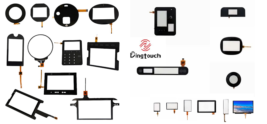
Custom-Shaped Touch Screens
Evaluate sensor manufacturability, FPC position, edge electrode design, cover glass curvature, and tooling costs. Confirm the drawings and manufacturing feasibility before committing to tooling.

11. DINGTouch Custom Touch Screen and Display Solutions
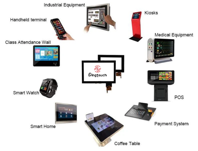
DINGTouch provides customized touch screen and touch display solutions for industrial, medical, and commercial equipment. Depending on project requirements, we can evaluate the sensor structure, cover glass design, touch controller, LCD panel, and bonding process.
Our customization scope can include:
-
Touch sensor structures: GF, GFF, GG, and other feasible capacitive touch designs.
-
Cover glass: Custom dimensions, irregular outlines, silk printing, and AF, AG, or AR surface treatments.
-
Touch functionality: Multi-touch, glove operation, wet-condition adaptation, and EMI optimization.
-
Display modules: LCD and touch screen assemblies with optical bonding or frame bonding.
-
Interfaces and system compatibility: Evaluation of touch interfaces such as USB and I²C, along with display interface compatibility based on project requirements.
Each project is evaluated according to the target structure, cover glass thickness, operating environment, controller configuration, and system requirements. Actual touch performance, optical specifications, and reliability must be verified through sample testing.
Learn more about customized solutions at the DINGTouch Official Website.
Frequently Asked Questions
Q1. What is the main difference between GF and GFF touch screens?
GF generally uses a single-layer film sensor, while GFF uses two film sensor layers. Multi-touch capability, thickness, and noise immunity depend on the specific electrode design and controller.
Q2. Is GG always better than GFF?
No. GG offers characteristics associated with glass sensors, including dimensional stability, while GFF can provide cost and manufacturing flexibility in selected custom applications. The best choice depends on performance requirements, mechanical design, environment, and budget.
Q3. What is the difference between OGS, On-cell, and In-cell?
OGS integrates the cover glass and touch sensor onto the same glass substrate. On-cell integrates the touch sensor into the upper structure of the display panel, while In-cell integrates touch sensing functionality within the display panel.
Q4. Which structure is suitable for thick cover glass and glove touch?
The answer depends on cover glass thickness, glove material, controller performance, and electrode design. The structure name alone cannot determine touch sensitivity. Prototype testing is recommended to verify sensitivity, noise immunity, and environmental performance.
Q5. What information is needed for a custom capacitive touch screen project?
Provide the display size and resolution, cover glass drawing, glass thickness, touch interface, target operating system, glove and wet-touch requirements, operating temperature, environmental protection requirements, and estimated order quantity. Complete information helps the engineering team evaluate the structure and development schedule more accurately.
Conclusion
GF, GFF, GF2, G1F, GG, OGS, On-cell, and In-cell represent different touch sensor structures and integration approaches. No single technology is ideal for every application.
The right touch screen structure must balance application requirements, touch performance, optical quality, manufacturing feasibility, and total project cost.
For industrial and customized display projects, evaluate the complete module, including the cover glass, touch controller, bonding process, LCD panel, and operating environment. This approach helps OEM buyers develop a more reliable and application-specific touch display solution with DINGTouch.




Ready to Build Your Outdoor Display Solution?
Get in touch with us at sales@szdingtouch.com. Our expert engineers will help you design a cost-effective, tailored solution to meet your project’s exact specifications.
DINGTouch:Committed to continuous innovation and improvement of product quality to meet customers' high requirements and expectations.
DINGTouch is a manufacturer that provides high quality touch screen panels. Focus on the design, manufacturing and sales of touch screen panels, and are committed to providing customized solutions that satisfy customers.
DINGTouch: In the process of customizing touch screen panels, we focus on close cooperation and communication with customers. Understanding customers' needs and providing customized solutions will meet customers' individual needs. The company's products are favored by customers for their high quality and reliability, and provide them with the best touchscreen panel solutions.
DINGTouch:Committed to continuous innovation and improvement of product quality to meet customers' high requirements and expectations.
DINGTouch is a manufacturer that provides high quality touch screen panels. Focus on the design, manufacturing and sales of touch screen panels, and are committed to providing customized solutions that satisfy customers.
DINGTouch: In the process of customizing touch screen panels, we focus on close cooperation and communication with customers. Understanding customers' needs and providing customized solutions will meet customers' individual needs. The company's products are favored by customers for their high quality and reliability, and provide them with the best touchscreen panel solutions.
At DINGTOUCH, we are the world's leading touchscreen manufacturer, helping businesses around the world take advantage of this exciting technology. For more information, please visit the home page now.

DINGTouch is a company specializing in the R&D and production of touch screen technology, headquartered in Shenzhen, China. As a professional touch screen supplier, DINGTouch is committed to providing high-quality, stable and reliable touch screen products to meet the diverse needs of customers. We continue to carry out technological innovation and product optimization to ensure that its touch screen products have good sensitivity, accuracy and durability.
In addition to the products themselves, we also focus on cooperation and communication with customers, and are committed to providing customized solutions and excellent after-sales services. Through continuous efforts to improve product quality and customer satisfaction, we have established a good reputation in the touchscreen industry and won widespread market recognition.
In addition to the products themselves, we also focus on cooperation and communication with customers, and are committed to providing customized solutions and excellent after-sales services. Through continuous efforts to improve product quality and customer satisfaction, we have established a good reputation in the touchscreen industry and won widespread market recognition.
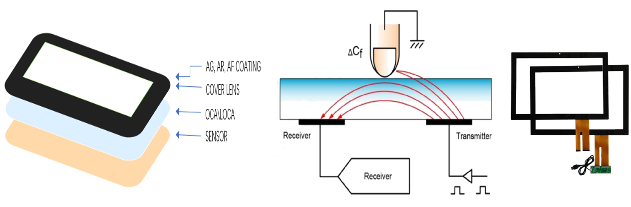
What DINGTOUCH can do:
• PCAP maximum size 65”
• Multi-touch (Touch screen can be customized to your needs.)
• Optical bonding service/air bonding
• LCD interface: HDMI/RGB/MIPI/LVDS/EDP, etc.
• PCAP interface: IIC/USB interface
• CTP can customize the cover glass surface treatment process AG (anti-glare), AR (anti-reflection), AF (anti-fingerprint), waterproof, and glove touch
• Supports 0.55 mm-12 mm coverslip touch.
• Support operating temperature: -40℃-90℃.
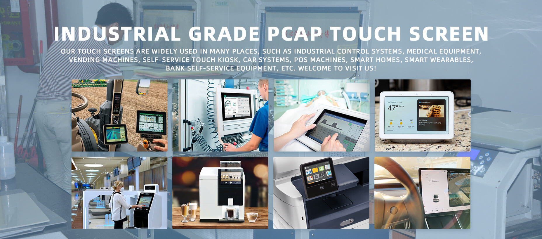
Dingtouch Industrial capacitive touch screen Manufacturer
In conclusion, Dingtouch as a professional touch screen manufacturer with more than 10 years touch screen experience.We have many capacitive touch screen. Such as 5 inch touch screen,7 inch touch screen,10.1inch touch screen,15 inch touch screen,15.6 inch touch screen,17 inch touch screen,18.5 inch touch screen,19 inch touch screen,21.5 inch touch screen,32 inch touch screen, However, we also welcome to customize your own touch screen . Contact our team today to learn what capacitive touch screen are best for our retail business needs.
Contact us NOW! sales@szdingtouch.com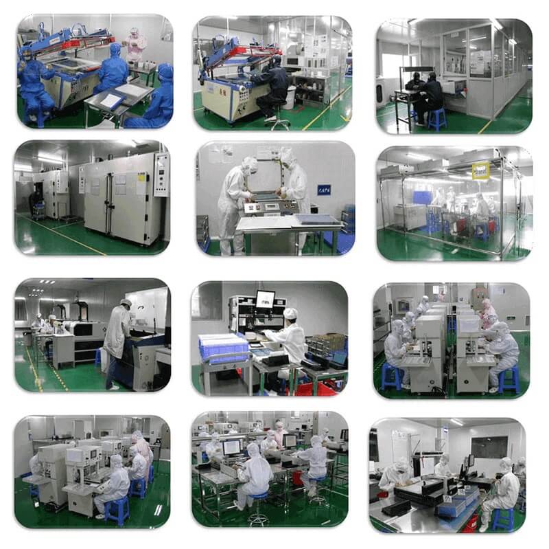
#Medicaltouchscreencalibration, #capacitivetouchcalibrationguide, #IEC60601touchscreen, #DINGTouchmedicaldisplay, #touchscreenaccuracy, #touchscreen driftfix, #medicalequipmenttouchsolutions, #IP65touchpanel, #IK10medicaltouchscreen, #glove touch medical monitor,#ILITEKTouchControllerICSelectionGuide ,#OCAtoOCR #GT911,#CustomizedWideTemperatureTouchScreenSolutions,#Waterproof Touchscreen,
#highbrightnessLCDPREVIOUS:21.5-Inch High-Brightness Mirror Touch Display: Customized LCD + PCAP Integration for Linux SystemsNo next
CATEGORIES
CONTACT US
Contact: Dingtouch
Phone: +8615815536116
Tel: +8615815536116
Email: sales@szdingtouch.com
Add: Building A, Bailu Plaza, No. 48, Gonghe Industrial Road, Gongle Community, Xixiang Street, Baoan District, Shenzhen,China. 518126
 Dingtouch