News
How to Diagnose an LCD That Is Slow, Flickers, or Fails to Start in Cold Temperatures
 How to Diagnose an LCD That Is Slow, Flickers, or Fails to Start in Cold Temperatures
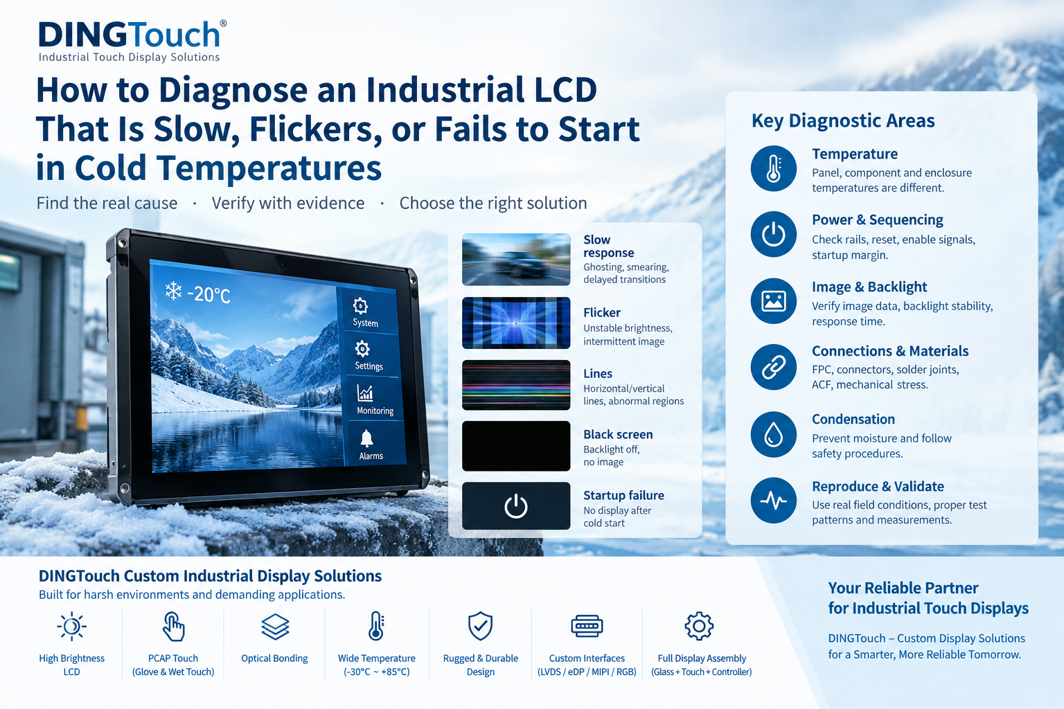
An industrial LCD may behave differently when the temperature drops. The image may become noticeably slower, the screen may flicker, horizontal or vertical lines may appear, or the display may fail to start normally after a cold soak.
However, not every cold-temperature display problem is caused by the LCD panel itself.
Low temperature can affect liquid-crystal response, but it can also change the behavior of power regulators, timing components, bridge IC, LED drivers, FPC, connectors, solder joints, batteries, and other components in the display system.
For industrial equipment, outdoor terminals, marine systems, EV charging equipment, medical devices, military equipment, and other demanding applications, the correct approach is therefore not simply to ask:
"Is the LCD rated for -20°C or -30°C?"
The more important questions are:
-
What exactly happens at low temperature?
-
Does the problem occur during startup or normal operation?
-
Is the image slow, unstable, dark, or completely missing?
-
Does the backlight remain active?
-
Are power rails and reset signals stable?
-
Does the problem disappear after warming?
-
Is condensation involved?
-
Can the complete display assembly meet the actual application requirement?
DINGTouch recommends treating cold-temperature LCD problems as a system-level diagnostic problem, rather than immediately assuming that the liquid-crystal panel is defective.
1. Classify the Cold-Temperature LCD Symptom Before Changing the Design
The first step is to create a repeatable description of the failure.
Record the display pattern, ambient temperature, local panel temperature, power state, startup sequence, backlight condition, interface status, and recovery behavior.
A statement such as "the screen fails at -20°C" is not enough for engineering analysis.
The failure could occur:
-
During cold startup
-
After a long cold soak
-
While the equipment is already operating
-
During temperature transition
-
Immediately after the backlight turns on
-
After condensation or rapid environmental changes
-
Only after repeated power cycles
Each condition points toward a different potential mechanism.
1.1 Slow LCD Response Is Different From Flicker or Line Defects
A slow LCD response normally appears as:
-
Motion blur
-
Ghosting
-
Smearing
-
Delayed gray-level transitions
-
Slow image changes
This behavior can be related to the temperature-dependent response of the liquid-crystal material.
By contrast, flicker may indicate:
-
Backlight instability
-
Power supply fluctuation
-
Panel driving problems
-
Timing problems
-
Interface instability
-
Reset events
-
Protection circuitry
-
Marginal system power
Lines or abnormal regions can have completely different causes, including:
-
FPC connections
-
Driver IC
-
ACF bonding
-
ZIF connectors
-
Solder joints
-
Mechanical stress
-
Timing or signal problems
-
Temperature-dependent contact changes
Therefore, the visual symptom should be classified before selecting a corrective action.
1.2 Determine Whether the Screen Is Black or the Backlight Is Off
A "black screen" does not necessarily mean that the LCD is not working.
Possible conditions include:
-
The LCD is receiving black image data.
-
The backlight is not operating.
-
The panel has not completed initialization.
-
The power sequence is incorrect.
-
The interface is not transmitting valid image data.
-
A controller, bridge IC, or processor has failed to start.
-
A protection circuit has been triggered.
Check the backlight, panel power rails, reset signal, interface activity, and image data before concluding that the LCD panel has failed.
If the display works after warming up, this is useful evidence—but it does not automatically prove that the liquid crystal was the root cause.
The component that warms first may be a regulator, processor, bridge IC, connector, oscillator, LED driver, or another part of the system.
1.3 Recovery Behavior Is Part of the Failure Diagnosis
Record how the display recovers.
Does it recover:
-
While remaining powered?
-
After a software reset?
-
After complete power removal?
-
After the panel warms?
-
After the enclosure warms?
-
After condensation disappears?
A reversible slow response within the specified operating range is very different from a persistent line defect, repeated reset, unstable backlight, or moisture-related failure.
1.4 Record the Complete Temperature and Power Timeline
Before repeatedly reproducing the problem, record the complete sequence:
Cold soak → power-on → backlight → initialization → first image → failure → operator action → recovery
Also record:
-
Ambient temperature
-
LCD surface temperature
-
Controller temperature
-
Power supply condition
-
Input voltage
-
Backlight brightness
-
Enclosure temperature
-
Humidity
-
Heating or fan operation
-
Power-off duration
-
Startup time
-
Software and firmware state
Existing system logs should be preserved whenever possible.
Boot messages, reset causes, power-good signals, brightness commands, bridge status, touch-controller status, and application timestamps can provide valuable evidence.
2. Understand Which Cold-Sensitive Mechanism Matches the Symptom
Once the symptom has been classified, build a mechanism model.
The objective is not to find the most familiar explanation. The objective is to identify the smallest mechanism that can explain the observed evidence.
2.1 Low Temperature Can Slow Liquid-Crystal Response
Liquid-crystal materials can become more viscous as temperature decreases. This can increase the time required for molecules to change orientation, resulting in slower pixel transitions.
Research on liquid-crystal mixtures has demonstrated temperature-dependent changes in rotational viscosity and elastic behavior.
For industrial applications, this means that a display may remain electrically functional at low temperature while its image response becomes slower.
However, the exact behavior depends on:
-
LCD mode
-
Liquid-crystal material
-
Cell structure
-
Temperature
-
Drive conditions
-
Gray-to-gray transition
-
Overdrive implementation
-
Refresh rate
-
Panel construction
Therefore, a room-temperature response-time specification should not automatically be treated as the performance at the cold operating limit.
2.2 Evaluate LCD Response Against the Real Application
Response time should be evaluated against the actual operator task.
For example:
-
Static industrial HMI
-
Camera monitoring
-
Vehicle display
-
Navigation system
-
Medical equipment
-
Industrial control panel
-
Outdoor kiosk
-
EV charging interface
A black-to-white transition may look acceptable in a laboratory test while certain gray-to-gray transitions still produce visible trails.
For this reason, define:
-
Test pattern
-
Initial luminance
-
Target luminance
-
Temperature
-
Stabilization time
-
Refresh condition
-
Overdrive condition
-
Measurement method
-
Acceptance criterion
The final question should not simply be:
"What is the response time?"
It should be:
"Does the display perform the required visual task at the lowest operating temperature?"
2.3 Cold Startup Can Reduce Power and Sequencing Margin
Low temperature can affect more than the LCD cell.
Temperature-dependent behavior may occur in:
-
DC/DC regulators
-
Oscillators
-
Crystals
-
Reset supervisors
-
Bridge ICs
-
Level shifters
-
LED drivers
-
Batteries
-
Passive components
-
Connectors
-
FPCs
During startup, inrush current, voltage ramp rate, load timing, and protection thresholds can become critical.
A power rail may eventually reach its nominal voltage but still violate the required startup sequence during the first milliseconds.
For this reason, a cold-start investigation should record:
-
Power rails
-
Power-good signals
-
Reset
-
Clock
-
Panel enable
-
Backlight enable
-
Interface state
-
Startup timing
-
Local temperature
These signals should be analyzed on the same time axis whenever possible.
2.4 Separate Startup Margin From Steady-State Margin
A display that operates normally at -30°C is not necessarily guaranteed to start normally at -30°C.
These are two different conditions.
For example:
-
A regulator may support the running load but fail during cold inrush.
-
An oscillator may eventually stabilize but start too slowly.
-
A bridge IC may work after manual reset but fail during automatic startup.
-
A controller may require a specific power sequence that is not maintained during cold startup.
Therefore, test cold startup and cold steady-state operation separately.
Repeated startup tests should be performed under the same stabilized conditions before changing the design.
Intermittent success should not automatically be considered a pass.
It can be evidence of insufficient engineering margin.
2.5 Temperature Can Expose Marginal FPC and Connector Problems
Temperature changes mechanical dimensions and material behavior.
Potentially affected components include:
-
FPC
-
ZIF connectors
-
ACF bonds
-
Solder joints
-
Gaskets
-
Bezels
-
Chassis components
-
Mechanical mounting points
If a line or abnormal region changes when temperature changes, do not immediately conclude that the LCD cell is defective.
Check whether the symptom correlates with:
-
Temperature
-
Connector position
-
Mounting torque
-
Enclosure deformation
-
FPC routing
-
Mechanical stress
Avoid unapproved pressure tests on an active display. Pressing the panel can create temporary optical changes, damage a marginal bond, or eliminate useful evidence.
2.6 Condensation Is a Different Cold-Temperature Problem
Condensation should be considered separately from normal low-temperature LCD behavior.
A surface may fall below the local dew point during:
-
Rapid environmental changes
-
Cold startup
-
Power loss
-
Cleaning
-
Rain exposure
-
Movement between indoor and outdoor environments
-
Rapid enclosure cooling
Moisture may appear:
-
Outside the cover glass
-
Between optical layers
-
Inside the enclosure
-
Around connectors
-
Near electronic components
If liquid or condensation is visible around energized electronics, normal operation should be stopped and the equipment should follow its approved isolation and service procedure.
Do not simply power the system to "warm it up" before assessing the moisture condition.
3. Reproduce the Cold-Temperature Transition With the Right Measurements
A useful environmental test should reproduce the actual field event rather than simply comparing two temperature endpoints.
Define:
-
Starting condition
-
Cooling profile
-
Dwell time
-
Power state
-
Startup sequence
-
Humidity
-
Orientation
-
Recovery condition
-
Temperature measurement locations
The actual field environment and product mission should determine the test conditions.
There is no single universal cold-soak temperature or duration that is appropriate for every industrial display.
3.1 Measure the Temperature of the Relevant Component
Ambient chamber temperature is not necessarily the same as:
-
LCD cell temperature
-
Cover glass temperature
-
LED board temperature
-
Controller temperature
-
Bridge IC temperature
-
Connector temperature
-
Enclosure temperature
Internal heat generation can create significant temperature gradients.
For reliable analysis, document:
-
Sensor location
-
Sensor attachment method
-
Calibration
-
Response time
-
Measurement uncertainty
DINGTouch recommends evaluating the actual display assembly, rather than relying only on the environmental chamber's displayed temperature.
3.2 Use Test Patterns That Separate Different Image Mechanisms
Different patterns reveal different problems.
A useful cold LCD test may include:
-
Moving high-contrast edges
-
Multiple gray-level transitions
-
Full red
-
Full green
-
Full blue
-
White
-
Black
-
One-pixel grid
-
Border patterns
-
Static reference regions
A moving image alone is not sufficient because it combines:
-
Rendering
-
Buffer presentation
-
Raster scanning
-
Interface transmission
-
Pixel response
-
Camera exposure
The purpose of a diagnostic pattern is to isolate one mechanism at a time.
3.3 Compare Powered and Unpowered Temperature Transitions
A useful comparison is:
Cold soak while powered
versus
Cold soak while unpowered, followed by cold startup
The two tests can reveal different failure mechanisms.
If the problem appears only after the display has been powered down and cooled, startup sequencing or component startup margin becomes more important.
If the problem gradually increases while the display remains operational, temperature-dependent image response or another steady-state mechanism may be more relevant.
Always remain within the product's safety and environmental limits during this comparison.
3.4 Challenge the Leading Hypothesis With a Controlled Change
Once one hypothesis becomes more likely, design a test that could either support or weaken it.
For example:
If LCD response is suspected
Keep power, backlight, raster, and interface stable and compare timed gray-level transitions.
If the image interface is suspected
Verify stable raster transmission, bridge status, cable integrity, and receiver behavior before evaluating LCD response.
If the backlight is suspected
Compare the backlight command with electrical or optical output.
If power sequencing is suspected
Synchronize power rails, reset, enable signals, clock, and interface activity.
The prediction should be written down before the test.
This helps prevent a common engineering mistake:
"The display worked after warming up, therefore the LCD liquid was the problem."
Warming can change many components simultaneously.
4. Decide Whether the Display Can Be Accepted, Corrected, or Redesigned
The final outcome is not always "replace the LCD."
The evidence may show:
-
Normal but slower cold response
-
Unacceptable image performance
-
Insufficient startup margin
-
Marginal interconnection
-
Backlight instability
-
Condensation
-
Incorrect system configuration
-
Operation outside the intended mission
4.1 Accept Performance Against a Defined Application
A display can be technically functional but still unsuitable for the customer's application.
Define the actual task:
-
Reading static information
-
Tracking moving objects
-
Monitoring a camera
-
Responding to alarms
-
Operating a touchscreen
-
Controlling industrial equipment
-
Viewing outdoor information
Then define measurable acceptance criteria.
For example:
-
Minimum readable text update
-
Maximum acceptable ghosting
-
Maximum startup time
-
No visible flicker
-
Stable backlight
-
Stable touch operation
-
No line defects
-
Successful startup after defined cold soak
This creates a much stronger engineering release criterion than simply stating:
"The LCD works at -30°C."
4.2 Select the Correct Corrective Strategy
Depending on the evidence, possible solutions may include:
LCD and liquid-crystal optimization
Select a panel and liquid-crystal configuration with verified low-temperature response.
Power and startup optimization
Adjust startup sequencing within the approved component requirements.
Interconnect improvement
Improve FPC routing, connector selection, bonding, soldering, or mechanical design.
Thermal management
Use controlled enclosure heating or other thermal management where appropriate.
Backlight optimization
Review LED driver, current regulation, brightness control, and protection behavior.
Condensation protection
Improve sealing, ventilation, thermal gradients, moisture control, or enclosure design.
Mission-temperature definition
If the product's actual mission permits it, define a realistic operating and startup temperature range based on verified system behavior.
Every corrective action creates additional verification requirements.
For example, a heater requires evaluation of:
-
Thermal model
-
Sensor position
-
Control logic
-
Warm-up time
-
Power consumption
-
Overtemperature protection
-
Power-failure behavior
-
Temperature uniformity
-
Condensation behavior
A heater is therefore not a universal solution for cold-start problems.
4.3 Verify the Complete Display After the Correction
After implementing a corrective action, repeat the original failure sequence.
Verify:
-
LCD image quality
-
Touch performance
-
Backlight
-
Power stability
-
Interface stability
-
Startup
-
Recovery
-
Temperature distribution
-
Sealing
-
Condensation behavior
The corrected configuration should then be reflected in:
-
Controlled drawings
-
BOM
-
Software
-
Test procedures
-
Environmental specifications
-
Production inspection
-
Service documentation
This closes the engineering evidence loop.
5. Common Questions About LCD Cold-Temperature Performance
5.1 Is a Slow LCD at Low Temperature Always Defective?
No.
Lower temperatures can increase liquid-crystal response time, and some reversible slow-response behavior may be consistent with the documented operating conditions.
The correct question is whether the display still meets the required application task.
Persistent lines, repeated resets, moisture, abnormal flicker, startup failure, or operation outside specifications require separate investigation.
5.2 Does a Wide Operating Temperature Range Guarantee Normal Motion Performance?
No.
A wide operating-temperature specification defines an environmental operating boundary under specified conditions.
It does not automatically guarantee:
-
Every gray-to-gray response
-
Motion quality
-
Startup time
-
Backlight stability
-
Touch performance
-
Interface stability
-
Complete-system user experience
For demanding industrial applications, buyers should request application-relevant performance evidence at the actual temperature range.
5.3 Can a Cabinet Heater Solve Every Cold-Start Problem?
No.
A heater may help maintain component temperature, but it cannot solve:
-
A defective connection
-
Incorrect power sequencing
-
Unsupported interface configuration
-
Marginal bridge behavior
-
Backlight driver problems
-
Uncontrolled condensation
Heating also introduces additional power consumption, thermal gradients, control requirements, and safety considerations.
6. What Evidence Should Be Included in a Cold LCD Evaluation?
For an industrial LCD or touch display project, the following information is particularly valuable:
Display information
-
LCD size
-
Resolution
-
Panel model
-
Interface
-
Brightness
-
Touch technology
-
Bonding structure
-
Backlight configuration
Environmental information
-
Operating temperature
-
Storage temperature
-
Humidity
-
Temperature transition rate
-
Cold-soak duration
-
Condensation conditions
Electrical information
-
Input voltage
-
Power rails
-
Reset
-
Enable signals
-
Backlight control
-
Interface timing
-
Startup sequence
Mechanical information
-
FPC routing
-
Connector type
-
Mounting structure
-
Bezel
-
Enclosure
-
Optical bonding
-
Mechanical stress points
Failure evidence
-
Photos or video
-
Temperature records
-
Startup waveform
-
Power logs
-
Interface status
-
Test pattern
-
Recovery behavior
-
Reproduction rate
The stronger the evidence package, the faster the root cause can be separated from competing hypotheses.
7. How DINGTouch Supports Custom Industrial LCD and Touch Display Projects
For industrial applications, selecting a "wide-temperature LCD" from a catalog is often only the beginning.
DINGTouch provides custom industrial touch display solutions for applications where temperature, brightness, durability, touch performance, and mechanical integration must work together.
Our engineering scope can include:
-
Industrial TFT LCD
-
High-brightness LCD
-
PCAP capacitive touch screen
-
Glove-touch solutions
-
Waterproof and wet-touch solutions
-
Optical bonding
-
Cover glass customization
-
G+G / G+F / G+F+F structures
-
HDMI display solutions
-
MIPI / LVDS / RGB / eDP interfaces
-
Custom FPC
-
Custom cover glass
-
AG / AR / AF surface treatment
-
EMI/EMC-oriented display structures
-
Wide-temperature display assemblies
-
Rugged industrial touch displays
For demanding projects, DINGTouch can evaluate the LCD + touch + cover glass + bonding + controller + mechanical structure as a complete display assembly rather than treating each component separately.
This is particularly important for:
-
Outdoor industrial equipment
-
EV charging systems
-
Marine equipment
-
Medical equipment
-
Industrial automation
-
Energy systems
-
Transportation
-
Military and rugged equipment
-
Smart terminals
-
Control panels
With approximately 15 years of industrial touch display customization experience, DINGTouch focuses on matching display performance to the customer's actual operating environment and product requirements.
8. Final Checklist: Before Releasing an LCD for Cold-Temperature Operation
Before approving an industrial LCD or touch display for production, confirm:
Symptom
-
Is the failure clearly classified?
-
Is it slow response, flicker, lines, dark screen, startup failure, or condensation?
Temperature
-
Is the actual LCD/panel temperature known?
-
Is the chamber temperature being confused with component temperature?
Power
-
Are the cold-start rails stable?
-
Are reset and enable sequences correct?
-
Is startup margin sufficient?
Image
-
Is the backlight stable?
-
Is the image data stable?
-
Is pixel response acceptable?
-
Are gray-to-gray transitions acceptable?
Touch
Does touch remain stable at the required temperature?
Does glove or wet-tou
CATEGORIES
CONTACT US
Contact: Dingtouch
Phone: +8615815536116
Tel: +8615815536116
Email: sales@szdingtouch.com
Add: Building A, Bailu Plaza, No. 48, Gonghe Industrial Road, Gongle Community, Xixiang Street, Baoan District, Shenzhen,China. 518126
 Dingtouch