News
ESP32-P4 MIPI DSI Display: How to Select a 2-Lane MIPI LCD
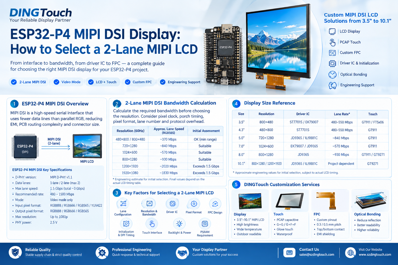
ESP32-P4 MIPI DSI Display: How to Select a 2-Lane MIPI LCD
Choosing the right MIPI DSI display for ESP32-P4 is not simply a matter of matching screen size and resolution. The MIPI lane configuration, bandwidth, DSI video mode, LCD driver IC, initialization sequence, DPI timing, FPC pinout, touch interface, and PSRAM requirements all affect whether the display can work reliably.
For developers building industrial HMI, embedded control panels, handheld instruments, smart devices, and other ESP32-P4 products, DINGTouch provides custom MIPI DSI LCD and capacitive touch display solutions from 3.5" to 10.1", including customized FPC, touch integration, optical bonding, high-brightness displays, and engineering support.
This guide explains how to select a 2-lane MIPI DSI display for ESP32-P4, how to estimate MIPI bandwidth, and which display parameters should be confirmed before ordering samples.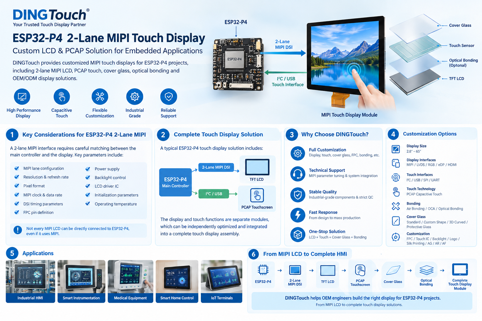
1. Understanding ESP32-P4 MIPI DSI Display Requirements
MIPI DSI, or MIPI Display Serial Interface, is a high-speed serial interface designed to connect a processor with a display panel.
Compared with a conventional parallel RGB interface, MIPI DSI requires fewer signal lines while providing high-speed data transmission. This makes it particularly suitable for compact embedded products where PCB space, FPC routing, EMI, and connector size are important.
For an ESP32-P4 display project, however, the first question should not be:
“Which MIPI LCD has the highest resolution?”
Instead, the correct question is:
“Can this MIPI LCD operate within the ESP32-P4's 2-lane DSI bandwidth and Video mode requirements?”
This distinction can eliminate many incompatible displays before hardware development begins.
2. ESP32-P4 MIPI DSI: 2-Lane and Video Mode
The ESP32-P4 MIPI DSI interface supports up to two data lanes.
According to the technical information in this project, the main parameters include:
| Parameter | ESP32-P4 Specification |
|---|---|
| D-PHY | MIPI D-PHY v1.1 |
| Data lanes | 1-lane / 2-lane |
| Maximum speed per lane | Up to 1.5 Gbps |
| Total theoretical bandwidth | Approximately 3 Gbps |
| Recommended lane-rate range | 480–1500 Mbps |
| DSI mode | Video mode |
| Input pixel formats | RGB888 / RGB666 / RGB565 / YUV422 |
| Output pixel formats | RGB888 / RGB666 / RGB565 |
| Display resolution | Up to 1080p |
| PHY supply | 2.5 V |
The 2-lane limitation is a hardware characteristic of the D-PHY, rather than something that can simply be changed through firmware.
Therefore, when selecting an MIPI LCD for ESP32-P4, the display should support a 1-lane or 2-lane configuration.
ESP32-P4 Requires MIPI DSI Video Mode
Another important point is the DSI operating mode.
The ESP32-P4 DSI host in this application uses Video mode, meaning that the host continuously transmits video frames according to the display timing.
This creates two important design requirements:
- The LCD must support continuous video transmission.
- The frame buffer is handled on the ESP32-P4 side, so PSRAM capacity and memory bandwidth must be considered during display selection.
This is especially important when using higher-resolution displays such as 800×1280, 1200×1920, or 1920×1080.
3. How to Choose a 2-Lane MIPI LCD for ESP32-P4
When selecting an ESP32-P4 MIPI display, DINGTouch recommends checking the following parameters in order:
- MIPI lane configuration
- Resolution and bandwidth
- DSI Video mode compatibility
- LCD driver IC
- Pixel format
- D-PHY hardware requirements
- FPC pin definition
- Initialization sequence and DPI timing
- Touch interface
- Backlight and power requirements
The goal is not simply to find a display that can theoretically work, but to find a display with a complete and practical hardware and software integration path.
3.1 1-Lane or 2-Lane MIPI DSI?
ESP32-P4 supports both 1-lane and 2-lane configurations.
A 1-lane design reduces the number of differential pairs and simplifies PCB routing. However, it also significantly reduces available bandwidth.
For lower-resolution displays such as 480×800 or 800×480, 1-lane MIPI DSI may be sufficient depending on pixel format and refresh rate.
For displays of 5 inches and above, 2-lane MIPI DSI is generally more practical because it provides additional bandwidth for higher resolutions.
Key point when sourcing an LCD
Do not only ask the supplier:
“Is this a MIPI LCD?”
Instead, ask:
“Does this panel support 2-lane MIPI DSI, and can you provide the corresponding 2-lane initialization sequence?”
Some LCD driver ICs commonly used in MIPI displays can be configured for different lane numbers. However, the actual initialization commands depend on the specific panel and driver configuration.
4. MIPI DSI Bandwidth: Calculate Before Choosing Resolution
One of the most important steps in ESP32-P4 display selection is calculating the required MIPI DSI bandwidth before finalizing the resolution.
The theoretical pixel data rate depends on:
- Horizontal resolution
- Vertical resolution
- Refresh rate
- Horizontal/vertical porch timing
- Pixel format
- Number of MIPI lanes
- Protocol overhead
- Design margin
For example, the original project calculation for an 800×1280 display at 60 Hz, RGB888, 2-lane MIPI DSI gives:
- Pixel clock ≈ 62.4 MHz
- Raw data rate ≈ 1497.6 Mbps
- Estimated protocol data rate ≈ 2153.6 Mbps
- Two-lane requirement ≈ 1076.8 Mbps per lane
- With an additional 20% design margin ≈ 1293 Mbps per lane
This remains within the stated 1.5 Gbps maximum per-lane range.
Therefore, bandwidth should be calculated together with the actual DPI timing parameters, rather than based only on the active resolution.
4.1 Typical 2-Lane MIPI Bandwidth Reference
For initial project evaluation, the following values from the original technical draft can be used as approximate references for 60 Hz RGB565:
| Resolution | Approx. Lane Speed | Initial Assessment |
|---|---|---|
| 480×800 / 800×480 | ~370 Mbps | Configure within the minimum recommended range |
| 720×1280 | ~840 Mbps | Suitable |
| 1024×600 | ~570 Mbps | Suitable |
| 800×1280 | ~930 Mbps | Suitable |
| 1200×1920 | ~2020 Mbps | Exceeds 1.5 Gbps at 60 Hz |
| 1920×1080 | ~1830 Mbps | Exceeds 1.5 Gbps at 60 Hz |
These figures are engineering estimates for preliminary screening , rather than final display timing values. Final lane rate and DPI timing should always be configured according to the selected LCD panel's datasheet and supplier-provided timing table.
5. RGB565 vs RGB666 vs RGB888
Pixel format has a direct impact on MIPI bandwidth and PSRAM requirements.
RGB565
16-bit color
Advantages:
- Lower bandwidth
- Lower frame-buffer memory requirement
- Suitable for many embedded HMI applications
- Provides more bandwidth margin for higher-resolution displays
For ESP32-P4 projects using 720×1280 or 800×1280, RGB565 can be a practical choice when bandwidth is limited.
RGB888
24-bit color
RGB888 provides a wider color range and is useful for applications requiring better gradients, image quality, and graphical effects.
However, it requires substantially more bandwidth than RGB565.
For smaller resolutions such as 1024×600, the bandwidth requirement may remain manageable depending on the refresh rate and timing.
RGB666
RGB666 provides 18-bit color, but its implementation can introduce additional complexity because different transmission formats may be used.
For many embedded display projects, the bandwidth savings compared with RGB888 may not justify the additional configuration complexity.
6. Choosing the Right MIPI LCD Driver IC
The LCD driver IC is another important factor.
Common MIPI driver ICs in ESP32-P4 display projects include:
- EK79007
- ILI9881C
- JD9365
- JD9165
- ST7701 / ST7703
- HX8399
- ER88577
- CO5300
- AXS15231B
- ST7121 / ST7123
- ST77916 / ST77922
- GC9503
However, the driver IC model alone does not guarantee compatibility.
The same driver IC can be used with different LCD panels, while the initialization sequence, gamma settings, power configuration, and timing parameters may vary.
Therefore, when sourcing an ESP32-P4 MIPI LCD, the following information is more useful than simply receiving an IC model number:
- Complete initialization commands
- 2-lane configuration
- DPI timing parameters
- Pixel format
- Reset sequence
- Power-on sequence
- Backlight control
- ESP-IDF integration information
This is one area where a display manufacturer with engineering support can significantly simplify development.
7. FPC Design Is Critical for ESP32-P4 MIPI Displays
MIPI DSI uses high-speed differential signals, so the FPC should not be treated as a simple connector.
DINGTouch can customize the FPC according to the customer's motherboard and mechanical design, including:
- Pin count
- Pin order
- 0.3 mm / 0.5 mm pitch
- FPC length
- Top/bottom contact
- Forward/reverse insertion
- EMI shielding
- Display + touch integration
- Backlight routing
Common FPC configurations include 20-pin, 24-pin, 30-pin, 31-pin, 40-pin, and 50-pin designs.
More importantly, the actual signal assignment needs to be checked rather than simply matching the pin count.
Typical MIPI DSI signals include:
- DSI_CLK_P/N
- DSI_D0_P/N
- DSI_D1_P/N
- RESET
- Power rails
- Backlight
- Touch I2C signals
A customized FPC can eliminate the need for an additional adapter board and help simplify the high-speed signal path.
8. MIPI DSI PCB Routing and Hardware Considerations
Because MIPI DSI is a high-speed differential interface, PCB routing should be considered during the early design stage.
Important considerations include:
- 100 Ω differential impedance
- Differential pair length matching
- Clock/data lane matching
- Short and direct routing
- Minimizing vias
- Avoiding unnecessary stubs
- Proper FPC connector design
- ESD protection near the connector
The original design guidance also identifies the 2.5 V DSI PHY supply as an important power consideration.
A stable PHY supply and correct FPC orientation should be verified before firmware debugging.
In practical development, some apparent “software problems” are actually caused by:
- Incorrect D0/D1 wiring
- Reversed FPC orientation
- Incorrect pin assignment
- Poor connector contact
- Incorrect reset timing
- Incorrect power sequence
9. Initialization Code and DPI Timing: What Should the Supplier Provide?
For an ESP32-P4 MIPI DSI project, DINGTouch recommends requesting the following information from the LCD supplier before starting integration:
1. Complete Initialization Sequence
The supplier should provide the required display register commands and execution order.
2. DPI Timing Table
The timing information should include:
- Resolution
- Pixel clock
- HSPW
- HBP
- HFP
- VSPW
- VBP
- VFP
- Synchronization polarity
3. 2-Lane Configuration
If the driver IC can support different lane configurations, confirm that the supplier can provide the 2-lane register configuration required by ESP32-P4.
This information can significantly reduce the time spent debugging an otherwise functional LCD panel.
10. ESP32-P4 + MIPI LCD + Capacitive Touch
MIPI DSI is used for display transmission. The capacitive touch controller normally communicates through a separate interface, most commonly I2C.
Typical touch signals include:
- SCL
- SDA
- INT
- RST
- 3.3 V power
Common touch controller options include:
- GT911
- GT9271
- FT5x06
- FT6336
- CST8xx
The touch controller may share the same FPC with the LCD, but its communication remains electrically separate from the MIPI DSI display data path.
For a complete ESP32-P4 touch display module, the LCD, PCAP sensor, cover glass, FPC, controller IC, and mechanical structure should therefore be evaluated as one system.
11. ESP32-P4 MIPI LCD + LVGL Integration
A typical ESP32-P4 touch display architecture can be divided into four layers:
| Layer | Main Function |
|---|---|
| Application / UI | LVGL interface, controls and animations |
| LVGL Adapter | Display, touch and buffer management |
| ESP LCD / MIPI DSI | DSI bus, DPI panel and DMA |
| DSI PHY | MIPI lane configuration and PHY power |
The general display initialization flow is:
- Configure the DSI PHY power.
- Create the MIPI DSI bus.
- Configure the number of lanes and lane rate.
- Create the DSI panel interface.
- Configure DPI timing and pixel format.
- Send the LCD initialization sequence.
- Enable the display.
- Configure the backlight.
- Allocate frame buffers in PSRAM.
- Register the display and touch with LVGL.
- Start the LVGL application.
This architecture makes the display panel selection and initialization data particularly important during the early hardware-development stage.
12. PSRAM Requirements for High-Resolution ESP32-P4 Displays
The frame buffer is an important part of an ESP32-P4 display design.
For example, an 800×1280 RGB565 frame requires approximately 2.05 MB of memory.
With double buffering, the requirement increases to approximately 4.1 MB, while triple buffering requires approximately 6.1 MB.
Therefore, when selecting an 800×1280 or larger display, developers should evaluate:
- PSRAM capacity
- Number of frame buffers
- LVGL draw buffer size
- DMA transfer
- Anti-tearing strategy
- Rotation requirements
For larger displays, memory planning should be performed together with MIPI bandwidth planning rather than treated as a separate software issue.
13. ESP32-P4 2-Lane MIPI LCD Selection by Display Size
For initial project evaluation, DINGTouch can support a range of MIPI LCD sizes.
| Display Size | Typical Resolution | Common Driver IC | Approx. Lane Rate* | Touch |
|---|---|---|---|---|
| 3.5" | 800×480 | ST7701S / EK79007 | 480–550 Mbps | GT911 / FT5x06 |
| 4.3" | 480×800 | ST7701S | 480–550 Mbps | GT911 |
| 5.0" | 720×1280 | JD9365 / ILI9881C | ~840 Mbps | GT911 |
| 7.0" | 1024×600 | EK79007 / JD9165 | ~570 Mbps | GT911 |
| 8.0" | 800×1280 | JD9365 | ~930 Mbps | GT911 / GT9271 |
| 10.1" | 800×1280 / 1200×1920 | JD9365 / ILI9881C | Project dependent | GT9271 |
*Approximate engineering values for initial selection, based on the original technical calculation and subject to actual LCD timing.
13.1 3.5" MIPI DSI LCD
A 3.5-inch 800×480 display has relatively low bandwidth requirements.
It can be suitable for:
- Portable instruments
- Small industrial controllers
- Handheld devices
- Compact HMI products
Depending on the pixel format and refresh rate, either 1-lane or 2-lane MIPI DSI can be considered.
13.2 4.3" MIPI DSI LCD
4.3-inch displays are commonly available in 480×800 portrait or 800×480 landscape configurations.
For ESP32-P4 projects, the key considerations are generally:
- Display orientation
- Brightness
- Touch configuration
- Backlight design
- Mechanical dimensions
- FPC configuration
13.3 5" 720×1280 MIPI DSI Display
At 720×1280, the bandwidth requirement becomes more important.
Under the original engineering calculation, RGB565 at 60 Hz requires approximately 840 Mbps per lane configuration basis, making a 2-lane design a practical choice.
This resolution is suitable for:
- Industrial handheld terminals
- Portable control equipment
- Embedded HMI
- Smart control devices
13.4 7" 1024×600 MIPI DSI Display
A 7-inch 1024×600 display offers a relatively comfortable bandwidth requirement under RGB565.
It can be used for:
- Industrial HMI
- Control panels
- Embedded terminals
- Measurement equipment
- Smart control systems
For outdoor or industrial applications, DINGTouch can additionally customize high-brightness LCD, PCAP touch, optical bonding, wide-temperature design and rugged cover glass according to project requirements.
13.5 8" and 10.1" MIPI DSI Displays
For 800×1280 displays, RGB565 provides considerably more bandwidth margin than RGB888.
For 1200×1920, however, 60 Hz exceeds the 2-lane bandwidth limit under the calculation in the original design.
Therefore, developers should evaluate:
- Resolution
- Refresh rate
- Pixel format
- MIPI lane rate
- PSRAM
- Application animation requirements
before selecting a 10.1-inch panel.
14. Custom ESP32-P4 MIPI Display Solutions from DINGTouch
For embedded projects that cannot use a standard LCD module, DINGTouch provides customized display solutions around the customer's PCB and mechanical structure.
Customization can include:
Display
- 3.5"–10.1" MIPI LCD
- Custom resolution
- IPS TFT LCD
- High-brightness display
- Wide-temperature LCD
- Outdoor sunlight-readable display
Touch
- PCAP capacitive touch
- G+G / G+F+F structures
- Glove touch
- Waterproof touch
- Multi-touch
- Custom cover glass
FPC
- Custom pinout
- Custom length
- 0.3 mm / 0.5 mm pitch
- Top/bottom contact
- EMI shielding
- Display + touch integrated FPC
Optical Bonding
For applications requiring better outdoor readability and improved mechanical reliability, DINGTouch can integrate optical bonding between the LCD, touch sensor and cover glass.
This can help reduce internal reflections and improve the overall display assembly for industrial and outdoor environments.
15. Common ESP32-P4 MIPI Display Problems
| Problem | Possible Cause |
|---|---|
| Backlight is on but LCD remains black | Initialization sequence, lane rate, PHY power or reset timing |
| Display flickers | DPI timing, porch parameters, lane rate or FPC connection |
| Incorrect colors | RGB565/RGB666/RGB888 mismatch or RGB order |
| DSI link fails | Incorrect lane wiring or FPC pin definition |
| Display works after power-on but fails after programming | LCD retains previous configuration or reset/power sequence issue |
| Touch does not respond | I2C address, INT/RST timing or touch pin configuration |
| ESP32-P4 becomes unstable | DSI link, buffer or configuration issue |
The key principle is:
Check the hardware interface and initialization parameters before assuming the problem is caused by LVGL.
16. ESP32-P4 MIPI DSI Display Selection Checklist
Before ordering samples, we recommend confirming these parameters with the display supplier:
MIPI DSI
- 1-lane or 2-lane?
- Video mode supported?
- Maximum lane rate?
- Recommended lane rate?
- Required DPI timing?
LCD
- Resolution
- Refresh rate
- Pixel format
- Driver IC
- Operating temperature
- Brightness
- Backlight voltage/current
FPC
- Pin count
- Pin pitch
- Pin definition
- Contact side
- Insertion direction
- FPC length
- Shielding requirements
Touch
- Touch IC
- I2C/SPI
- I2C address
- INT/RST
- Glove touch requirement
- Waterproof requirement
Software
- Initialization commands
- 2-lane configuration
- DPI timing table
- ESP-IDF support
- LVGL integration information
FAQ: ESP32-P4 MIPI DSI Display
Can ESP32-P4 use a 4-lane MIPI LCD?
It depends on the LCD driver IC and its configuration. If the driver IC supports switching to a 2-lane configuration and the supplier can provide the correct initialization sequence, the panel may be usable with ESP32-P4.
Always confirm the 2-lane register configuration and initialization code before purchasing samples.
Does ESP32-P4 support MIPI DSI Command mode?
The technical configuration described in this guide is based on Video mode. Therefore, the selected display should be evaluated for Video mode operation rather than assuming Command mode compatibility.
Does the MIPI DSI interface carry touch data?
No. Touch communication is normally handled separately through I2C or SPI.
How much PSRAM is needed for an 800×1280 display?
For RGB565, one full frame is approximately 2.05 MB. Double or triple buffering increases the memory requirement accordingly.
Can DINGTouch customize the MIPI FPC?
Yes. DINGTouch can customize the FPC pinout, pitch, length, contact direction, shielding and integration of display, touch and backlight according to the customer's motherboard.
Can DINGTouch provide the initialization sequence?
For customized ESP32-P4 MIPI display projects, the display solution can be developed together with the required 2-lane configuration, initialization commands and DPI timing information for integration.
Conclusion: Selecting an ESP32-P4 MIPI DSI Display
Selecting a display for ESP32-P4 is not simply about choosing a screen with the desired size and resolution.
A successful ESP32-P4 MIPI DSI display solution should be evaluated as a complete system:
2-Lane MIPI DSI + Bandwidth + Driver IC + Initialization Code + DPI Timing + FPC + Touch + PSRAM + LVGL
For projects using 3.5"–10.1" MIPI LCD, DINGTouch can provide customized solutions covering the display panel, PCAP touch screen, cover glass, optical bonding, FPC, driver configuration and display integration.
If your project requires a 2-lane MIPI DSI LCD for ESP32-P4, send us your display size, resolution, target brightness, touch requirement, operating temperature and motherboard/FPC requirements. DINGTouch can evaluate the display architecture and recommend a suitable customized solution.
DINGTouch — Custom Industrial Touch Display Solutions
CATEGORIES
CONTACT US
Contact: Dingtouch
Phone: +8615815536116
Tel: +8615815536116
Email: sales@szdingtouch.com
Add: Building A, Bailu Plaza, No. 48, Gonghe Industrial Road, Gongle Community, Xixiang Street, Baoan District, Shenzhen,China. 518126
 Dingtouch